Rubber tube cutting machine

A rubber tube and cutting machine technology, applied in metal processing and other directions, can solve the problems of pulling deformation at the gap, affecting the appearance, and uneven cutting, so as to achieve the effect of neat gap and avoid pulling deformation

Inactive Publication Date: 2020-12-18
刘清杰
View PDF0 Cites 0 Cited by
  • Summary
  • Abstract
  • Description
  • Claims
  • Application Information

AI Technical Summary

Problems solved by technology

[0004] Aiming at the deficiencies in the prior art, the object of the present invention is to provide a rubber tube cutting machine to solve the problem of uneven force on both ends due to the unique toughness of the rubber tube when the cutting machine cuts the rubber tube. Generally, the incision is uneven, and the notch is also easy to be pulled and deformed, which affects the aesthetics of the overall processing.

Method used


Image

  • Rubber tube cutting machine
  • Rubber tube cutting machine
  • Rubber tube cutting machine

Examples


no. 1 example

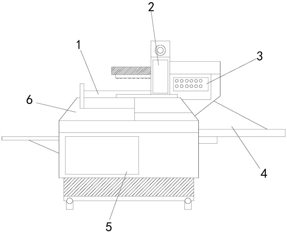
[0025] see Figure 1-Figure 2 , the present invention provides a rubber tube cutting machine technical solution: its structure includes: clamping platform 1, cutting knife group 2, controller 3, transfer platform 4, distribution box 5, protective cover plate 6, the controller 3 Installed on the right side of the cutting knife group 2 and electrically connected with the cutting knife group 2, a power distribution box 5 is arranged below the controller 3, and the power distribution box 5 is locked with the controller 3, and the power distribution box 5 A clamping platform 1 is provided on the surface, and the clamping platform 1 is locked with the distribution box 5. A protective cover plate 6 is provided on the side of the clamping platform 1, and the protective cover plate 6 is locked with the clamping platform 1. Then, the right side of the clamping platform 1 is provided with a transfer platform 4, and the clamping platform 1 includes a fixed block device a, a telescopic fra...

no. 2 example

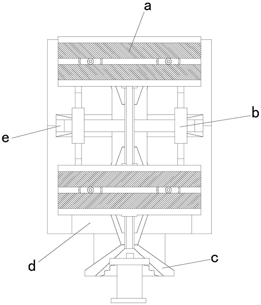
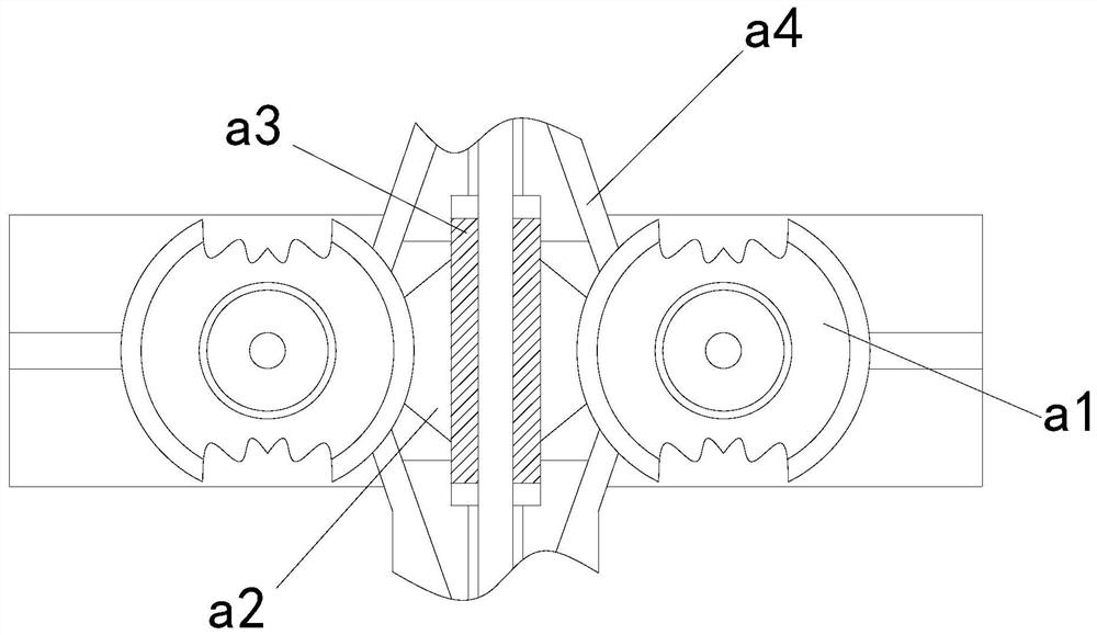
[0028] see Figure 3-Figure 5 , the present invention provides a rubber tube cutting machine technical solution: its structure includes: the fixed block device a includes a chuck device a1, a linkage groove a2, a movable groove block a3, and a track plate a4, and the chuck device a1 is installed on The inner side of the track plate a4 is buckled with the track plate a4, and the chuck device a1 is buckled with the movable slot block a3 through the linkage slot a2.

[0029] The chuck device a1 includes a connection buckle a11, a support disc a12, and an anti-skid plate a13. The anti-skid plate a13 is embedded in the inner side of the support disc a12, and the upper end of the support disc a12 is provided with a connection buckle a11. The disk a12 is locked, and the chuck device a1 performs non-slip cooperation with the outer wall of the rubber tube through the cooperation of the anti-skid plate a13.

[0030] The segmented frame device c includes a guide interlayer c1, a fixed b...


PUM


Abstract

The invention discloses a rubber pipe cutting machine. The rubber pipe cutting machine structurally comprises a clamping platform, a cutting knife set, a controller, a transfer platform, a distribution box and a protective cover plate. When the rubber pipe cutting machine is used, due to the arrangement of a clamping platform mechanism, the situation that when the cutting machine cuts a rubber pipe, due to the unique toughness of the rubber pipe, notches are uneven generally due to uneven stress at the two ends, meanwhile, the notches are prone to being pulled to deform, and the attractivenessof overall machining is affected is avoided, so that the equipment matches a moving rail of the rubber pipe through mutual cooperation of segmented frame devices, and the rubber pipe enters a presetrail of a fixing block device; and meanwhile, due to mutual cooperation of the fixing block device and a stretchable frame, the two end openings can be stably clamped within a short distance before cutting is conducted, the notches are neater, and meanwhile the situation that the notches are pulled to deform due to uneven stress is avoided.

Description

technical field [0001] The invention is a rubber tube cutting machine, which belongs to the field of cutting machine equipment. Background technique [0002] After more than 50 years of development, my country's rubber hose belt industry has played an indispensable supporting role in the national economy. Especially with the improvement of my country's mechanization level and the application of new materials, the rubber hose belt industry has continuously penetrated into related fields. It has opened up the application range and fields of rubber hose belts. With the development of the modern mechanical processing industry, the requirements for cutting quality and precision are continuously improved, and the requirements for improving production efficiency, reducing production costs, and having highly intelligent automatic cutting functions is also improving. [0003] The existing technology has the following disadvantages: when the rubber tube is cut by the cutting machine, d...

Claims


Application Information

Patent Timeline
Patent Type & Authority Applications(China)
IPC IPC(8): B26D7/01B26D7/02B26D7/06B26D7/00
CPCB26D7/00B26D7/01B26D7/02B26D7/06B26D2007/013
Inventor 刘清杰
Owner 刘清杰
Why Eureka
Try Eureka