
Milling fixture capable of achieving lifting and buffering after clamping

A fixture and shock-absorbing technology, applied in the direction of clamping, manufacturing tools, maintenance and safety accessories, etc., can solve the problems of increasing production costs, reducing production efficiency, affecting the accuracy of workpieces, etc., to achieve the effect of improving the production process

Inactive Publication Date: 2020-12-18
磐安字根电子科技有限公司
View PDF0 Cites 0 Cited by
  • Summary
  • Abstract
  • Description
  • Claims
  • Application Information

AI Technical Summary

Problems solved by technology

[0002] In traditional milling fixtures, it is often necessary to use different fixtures for different workpieces and to face different production processes and production requirements, and the fixtures to move in different positions in the milling machine, which not only reduces production efficiency but also increases The accuracy of the workpiece is affected when the fixture is replaced, and different fixtures need to be redesigned to produce different workpieces, which will lead to an increase in the production cost of the enterprise in the process of designing fixtures and producing fixtures. The shock milling fixture can solve the above problems

Method used


Image

  • Milling fixture capable of achieving lifting and buffering after clamping
  • Milling fixture capable of achieving lifting and buffering after clamping
  • Milling fixture capable of achieving lifting and buffering after clamping

Examples


Embodiment Construction

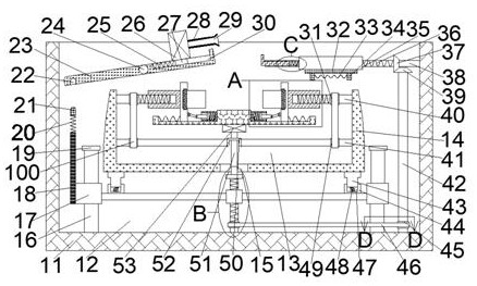
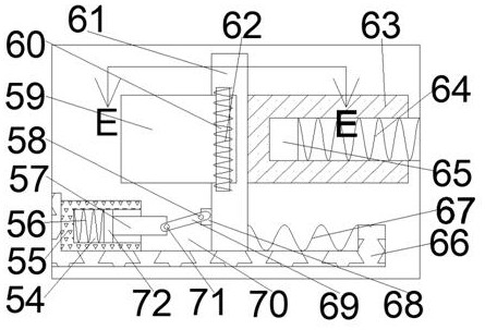
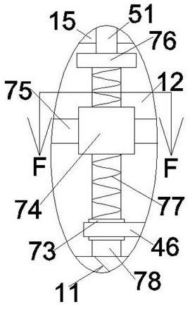
[0018] Combine below Figure 1-7 The present invention is described in detail, wherein, for the convenience of description, the orientations mentioned below are defined as follows: figure 1 The up, down, left, right, front and back directions of the projection relationship itself are consistent.

[0019]A milling fixture that can be lifted and clamped and cushioned according to the present invention includes a lifting box 11, in which a lifting cavity 12 with an upward opening is provided, and the front and rear walls of the lifting cavity 12 are slidably connected with Fixture box 14, the fixture box 14 is provided with a clamping chamber 13 with an upward opening, the lower wall of the clamping chamber 13 is provided with a through opening 15, and the through opening 15 communicates with the lifting chamber 12 and the clamping chamber. The holding chamber 13, the lower wall of the lifting chamber 12 is rotatably connected with a bottom shaft 78, the upper end of the bottom ...


PUM


Abstract

The invention discloses a milling fixture capable of achieving lifting and buffering after clamping. The milling fixture comprises a lifting box, a lifting cavity with an upward opening is formed in the lifting box, a fixture box is slidably connected to the front wall and the rear wall of the lifting cavity, a clamping cavity with an upward opening is formed in the fixture box, a through openingis formed in the lower wall of the clamping cavity, the through opening makes the lifting cavity communicate with the clamping cavity, a bottom rotating shaft is rotationally connected into the lowerwall of the lifting cavity, and a driving screw is fixedly connected to the upper end of the bottom rotating shaft. According to the milling fixture, when the fixture is used for milling operation, ablank can be located in the fixture, moreover, clamping of the fixture is achieved in addition, high-low lifting operation is conducted on the fixture according to different production requirements, so that the requirement of meeting different production requirements and different production processes is met, and during machining, the fixture can buffer vibration generated by a workpiece to ensurethat the vibration of the workpiece does not influence the precision of the workpiece, the fixture can meet the requirements of diversified production processes, so that the production efficiency isimproved.

Description

technical field [0001] The invention relates to the related fields of milling, in particular to a milling fixture that can be lifted and lowered and cushioned after being clamped. Background technique [0002] In traditional milling fixtures, it is often necessary to use different fixtures for different workpieces and to face different production processes and production requirements, and the fixtures to move in different positions in the milling machine, which not only reduces production efficiency but also increases The accuracy of the workpiece is affected when the fixture is replaced, and different fixtures need to be redesigned to produce different workpieces, which will lead to an increase in the production cost of the enterprise in the process of designing fixtures and producing fixtures. The shock milling fixture can solve the above problems. Contents of the invention [0003] In order to solve the above problems, this example designs a milling fixture that can be...

Claims


Application Information

Patent Timeline
IPC IPC(8): B23Q3/06B23Q1/25B23Q11/00
CPCB23Q1/25B23Q3/06B23Q11/0039B23Q11/0042
Inventor 张晓蝴
Owner 磐安字根电子科技有限公司
Learn More