Eureka AIR delivers breakthrough ideas for toughest innovation challenges, trusted by R&D personnel around the world.

Oblique angle cutting equipment for rectangular square pipe of electric power iron tower

A technology for rectangular square tubes and cutting equipment, which is applied in the direction of shearing machine equipment, metal processing equipment, shearing devices, etc., and can solve problems such as inconsistent cutting shapes, inability to connect rectangular square tubes incorrectly, and cumbersome workflow.

Active Publication Date: 2020-12-18
安徽宝光特钢集团万里电力铁塔有限公司
View PDF17 Cites 0 Cited by
  • Summary
  • Abstract
  • Description
  • Claims
  • Application Information

AI Technical Summary

Problems solved by technology

[0003] 1. The rectangular square tube of the traditional power tower is easy to cut when it is obliquely cut. In the later use process, corresponding welding adjustments need to be made according to the required cutting position, which makes the workflow cumbersome;
[0004] 2. When the rectangular square tube is cut at an oblique angle, the rectangular square tube is placed straight, which makes it difficult for the cutting blade to cut the rectangular steel tube, which makes the cutting shape inconsistent, resulting in the inability to connect the rectangular square tube incorrectly.

Method used


Image

  • Oblique angle cutting equipment for rectangular square pipe of electric power iron tower
  • Oblique angle cutting equipment for rectangular square pipe of electric power iron tower
  • Oblique angle cutting equipment for rectangular square pipe of electric power iron tower

Examples


Embodiment Construction

[0028] The embodiments of the present invention will be described in detail below with reference to the accompanying drawings, but the present invention can be implemented in many different ways as defined and covered by the claims.

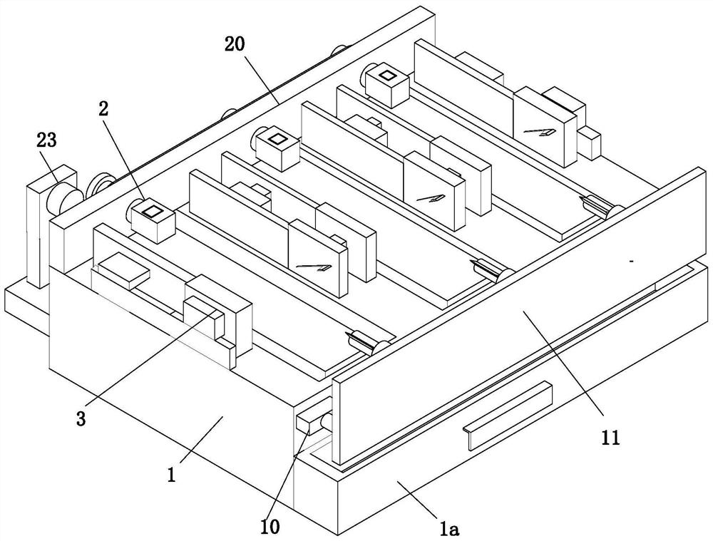
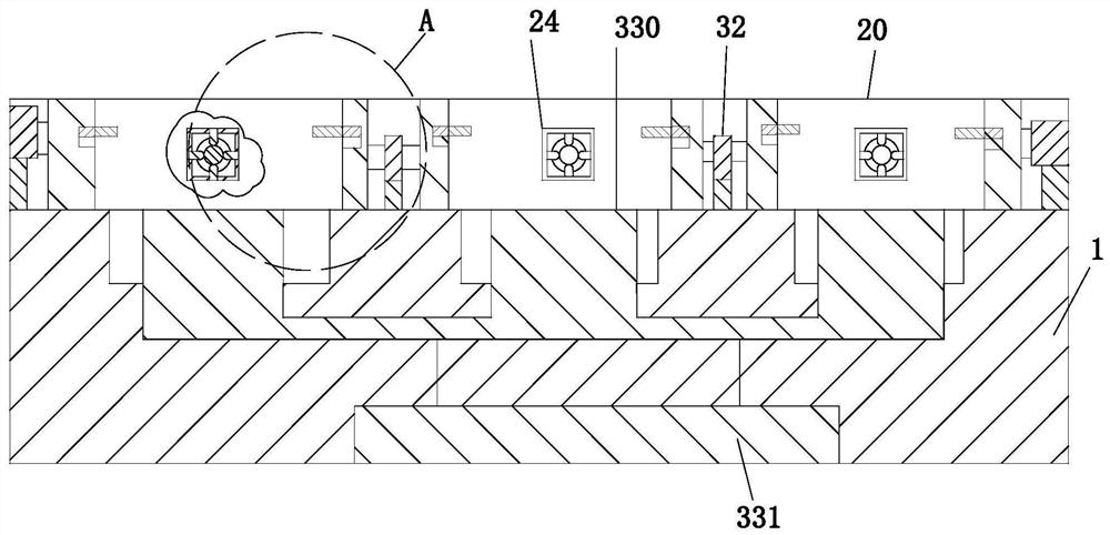
[0029] Such as Figure 1 to Figure 9 As shown, a kind of bevel cutting equipment for rectangular square tubes of electric power towers includes a workbench 1, a clamping and rotating mechanism 2 and a fixed cutting mechanism 3. The workbench 1 is installed on the working ground, and the rear end of the workbench 1 is installed There is a clamping and rotating mechanism 2, and a fixed cutting mechanism 3 is installed on the upper surface of the workbench 1.

[0030]A No. 1 electric cylinder 10 is installed on the front end of the workbench 1, and a connecting plate 11 is installed on the No. 1 electric cylinder 10. The front end of the connecting plate 11 is equipped with a rotating column 12 through a bearing, and the rotating column 12 is from l...


PUM


Abstract

The invention relates to oblique angle cutting equipment for a rectangular square pipe of an electric power iron tower. The oblique angle cutting equipment comprises a workbench, a clamping and rotating mechanism and a fixing and cutting mechanism, wherein the workbench is arranged on the working ground; and the clamping and rotating mechanism is arranged at the rear end of the workbench, and thefixing and cutting mechanism is arranged on the upper end face of the workbench. According to the oblique angle cutting equipment for the rectangular square pipe of the electric power iron tower, theadopted clamping and rotating mechanism can solve the rotating problem of the rectangular square pipe, the rectangular square pipe is fixed in the clamping and rotating mechanism, and then the required angle is adjusted and rotated, so that the cutting positions of the rectangular square pipe are the same; the left side and the right side of the rectangular square pipe are fixed through the fixingand cutting mechanism, and the rectangular square pipe is cut through obliquely-arranged cutting blades, so that the cutting positions of the rectangular square pipe are the same; and electric air cylinders two push oblique clamping plates to clamp the front end of the rectangular square pipe, so that the rectangular square pipe is prone to rotate in the rotating process, and meanwhile the oblique clamping plates do not influence cutting of the rectangular square pipe by the cutting blades.

Description

technical field [0001] The invention relates to the technical field of cutting, in particular to a bevel cutting device for a rectangular square tube of a power tower. Background technique [0002] Power towers generally refer to transmission line towers. Transmission line towers are tower-shaped buildings for power transmission. Their structural characteristics are that various tower types are space truss structures. The rods are mainly composed of single equilateral angle steel or combined angle steel. Generally, two types of Q235 (A3F) and Q345 (16Mn) are used. The connection between the rods is made of rough bolts, which are connected by bolts under shear force. The whole tower is composed of angle steel, connecting steel plates and bolts. The steel plates are welded into an assembly, so hot-dip galvanized anti-corrosion, transportation and construction erection are extremely convenient. For iron towers with a height below 60m, foot nails are set on one of the main mater...

Claims


Application Information

Patent Timeline
Patent Type & Authority Applications(China)
IPC IPC(8): B23D31/00B23D33/02B23D33/00B23Q11/00
CPCB23D31/00B23D33/00B23D33/02B23Q11/0067
Inventor 王少权常征
Owner 安徽宝光特钢集团万里电力铁塔有限公司
Why Eureka
Eureka Blog
Learn More