
Electrochemical water removal method and system for stripping liquid waste liquid

A stripping solution and electrochemical technology, applied in chemical instruments and methods, separation methods, water/sewage treatment, etc., can solve the problem of high energy consumption, and achieve the effect of realizing waste liquid recovery, zero energy consumption, and simple structure

Active Publication Date: 2020-12-15
南京博裕环境科技有限公司
View PDF6 Cites 2 Cited by
  • Summary
  • Abstract
  • Description
  • Claims
  • Application Information

AI Technical Summary

Problems solved by technology

Another technical problem to be solved by the present invention is to provide an electrochemical dewatering method for stripping liquid waste liquid, using the method of electrochemical reaction, which overcomes the shortcoming of high energy consumption in the prior art, makes water participate in the electrode reaction, consumes The water in the aqueous waste liquid not only has zero energy consumption, but also generates electricity, and also produces high-purity fine chemical products

Method used


Image

  • Electrochemical water removal method and system for stripping liquid waste liquid
  • Electrochemical water removal method and system for stripping liquid waste liquid

Examples


Embodiment 1

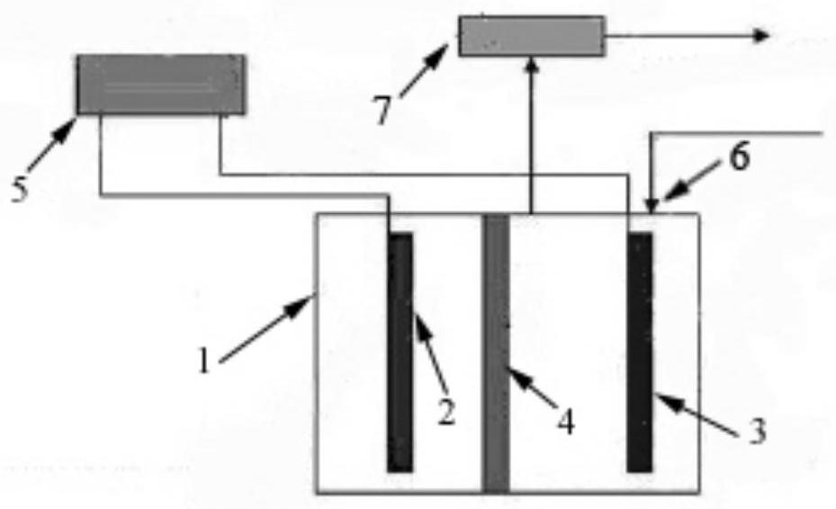
[0028] An electrochemical water removal system for stripping liquid waste liquid, the structure is as follows figure 1 shown. Depend on figure 1 It can be seen that the system includes an external power supply, a battery assembly, a waste liquid storage tank and a finished product storage tank; the battery assembly includes an electrochemical reaction cell casing 1, an air cathode 2, a metal anode 3 and an insulating diaphragm 4; the connection between the metal anode 3 and the air cathode 2 There is an insulating diaphragm 4 between them, the insulating diaphragm is a selectively permeable film, the material of the insulating diaphragm is thermosetting epoxy resin, and the insulating diaphragm is chemically compatible with the stripping liquid waste liquid.

[0029] Electrochemical reaction tank shell 1 is filled with electrolyte, which is the waste liquid of the stripper to be treated; metal anode 3 and air cathode 2 are connected to external power supply 5; electrochemical...

Embodiment 2

[0035] The electrochemical dewatering system in Example 1 is used to dewater the stripping liquid waste liquid. The stripping liquid waste liquid enters the inside of the electrochemical dewatering system through the liquid inlet and then flows through the metal anode, air cathode and insulating diaphragm. Consumed in the reaction process The anode metal and the water in the stripper waste liquid simultaneously form reactants in a precipitated state, achieving the purpose of material separation and water removal at the same time. Specifically include the following steps:

[0036] (1) The metal anode and the air cathode are connected to the external power supply respectively, and the water-containing stripping solution waste liquid (the composition of the Thinner100% dilution liquid waste liquid is shown in Table 1) enters the electrochemical water removal system through the liquid inlet of the shell, and simultaneously with The metal anode, the air cathode and the gas passing ...


PUM


Abstract

The invention discloses an electrochemical water removal method and system for stripping liquid waste liquid, and belongs to the technical field of wastewater recycling in the electronic manufacturingindustry. According to the method, stripping liquid waste liquid enters an electrochemical water removal system through a liquid inlet and then flows through a metal anode, an air cathode and an insulating diaphragm, anode metal and water in the stripping liquid waste liquid are consumed in the reaction process, reactants in a precipitation state are formed at the same time, and the purpose of water removal is achieved while substance separation is achieved. An electrochemical reaction method is used, the defect of high energy consumption in the prior art is overcome, water participates in anelectrode reaction, water in waste liquid is consumed, energy consumption is zero, electric energy is generated, and high-purity fine chemical products are produced again.

Description

technical field [0001] The invention belongs to the technical field of waste water recycling in electronic manufacturing industry, and in particular relates to an electrochemical dewatering method and system for stripping liquid waste liquid. Background technique [0002] In recent years, the domestic electronic manufacturing industry has developed rapidly, and the usage of electronic chemicals such as stripping fluid has also increased greatly. Usually, in the manufacturing process of liquid crystal display panels, semiconductor integrated circuits, etc., it is necessary to use a stripping solution to remove the photoresist coated on the microcircuit protection area as a mask. Commonly used stripping solutions mainly include a mixture of organic amines and polar organic solvents, and contain light components represented by a small amount of water. [0003] A large amount of stripping liquid waste is produced during the application of the stripping liquid, and except for a ...

Claims


Application Information

Patent Timeline
Patent Type & Authority Applications(China)
IPC IPC(8): C02F1/469
CPCC02F1/469
Inventor 赵世民
Owner 南京博裕环境科技有限公司
Learn More