A reciprocating plywood production device
A production device and plywood technology, applied in the direction of plywood presses, veneer presses, wooden veneer joints, etc., can solve problems such as burns, achieve the effects of reducing strokes, reducing labor intensity, and improving processing efficiency
- Summary
- Abstract
- Description
- Claims
- Application Information
AI Technical Summary
Problems solved by technology
Method used
Image
Examples
Embodiment 1
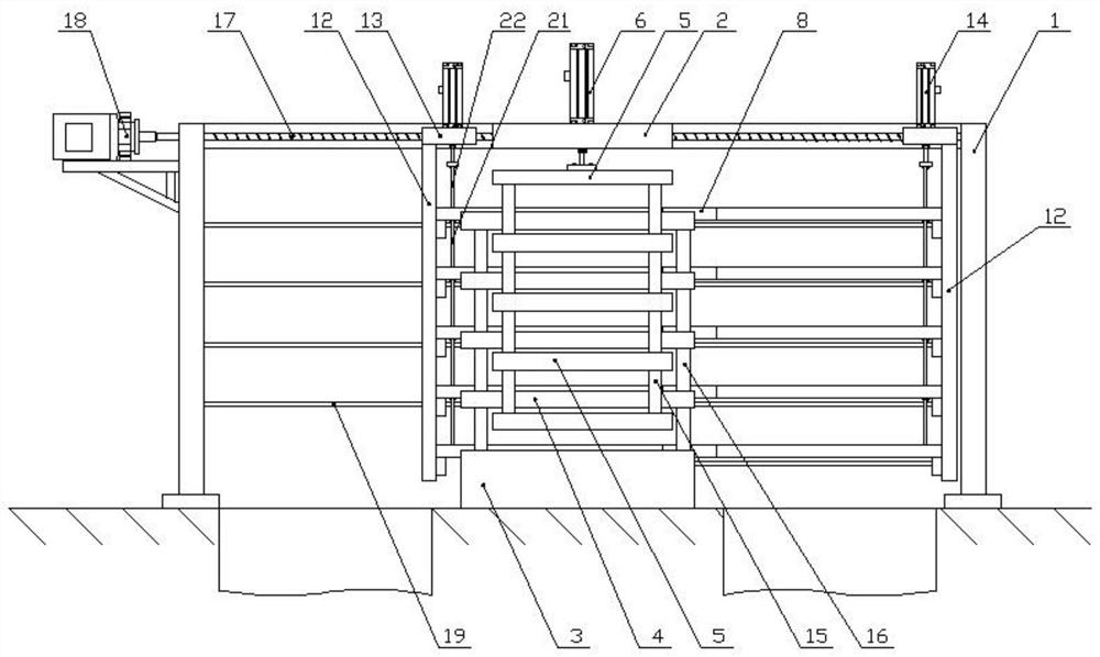
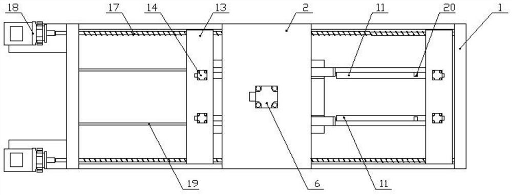
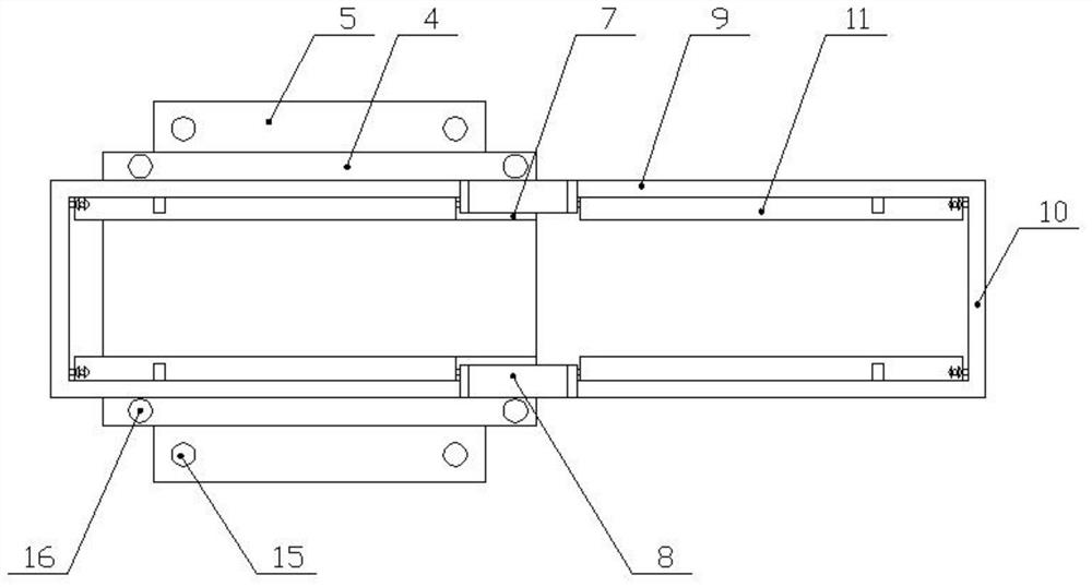
[0025] Embodiment 1: as Figure 1-Figure 4 As shown, the specific structure of this embodiment is as follows: it includes a frame 1, and the frame 1 includes vertical plates arranged at intervals, and the upper ends of the vertical plates on both sides are connected by transverse beams, and the middle part of the transverse beams is provided with a top wall 2, and the top wall 2 is provided with a hot-press driving device 6, and the hot-press driving device 6 can adopt linear actuators such as oil cylinders, hydraulic cylinders, and electric push rods; the piston rod of the hot-press driving device 6 is connected with the upper hot-press plate 5, and the upper hot-press The bottom of the plate 5 is provided with a lower hot-pressing plate 4, the lower hot-pressing plate 4 is arranged on the upper end of the base 3, and the upper end surface of the lower hot-pressing plate 4 is provided with a chute 7 through which both ends are connected at intervals, and the two ends of the ch...
Embodiment 2
[0027] Embodiment 2: as Figure 1-Figure 4 As shown, other structures in this embodiment are the same as in Embodiment 1, but in this embodiment, multiple slabs are processed at one time, and the upper hot pressing plate 5 and the lower hot pressing plate 4 are arranged at intervals along the vertical direction, and The upper hot pressing plate 5 and the lower hot pressing plate 4 are stacked in a staggered manner. A lower hot pressing plate 4 and the upper hot pressing plate 5 above it form a hot pressing unit. The wide sides of the press plate 4 are on the same side, so that the upper heat press plate 5 and the lower heat press plate 4 all partially protrude from the other side, and a support column 15 is arranged between the adjacent two upper heat press plates 5, and the adjacent two heat press plates 5 A vertical column 16 is arranged between the lower hot pressing plates 4, and the upper hot pressing plate 5 at the uppermost end is connected with the hot pressing driving...
Embodiment 3
[0029] Embodiment 3: as Figure 1-Figure 4As shown, the other structures in this embodiment are the same as in Embodiment 1, but in this embodiment, in order to ensure the synchronous movement of the two slab placing frames and reduce the driving mechanism, the two slab placing frames are respectively arranged in the connection of the chute 7. 8 sides, in this embodiment, only one limiting plate 20 can be provided and located at the far end of the connecting portion 8, at this time the slab is placed in the space formed by the connecting portion 8, the limiting plate 20 and the baffle plate 9 The upper end of the frame 1 is horizontally provided with a screw 17, the two ends of the screw 17 are respectively connected with the bearings in the vertical plates on both sides, the screw 17 passes through the through hole on the top wall 2, and the screw 17 passes through the through hole on the top wall 2. The rod 17 is threadedly connected with the sliding portion 13, and the fram...
PUM
 Abstract
Description
Claims
Application Information
 - R&D
- Intellectual Property
- Life Sciences
- Materials
- Tech Scout
- Unparalleled Data Quality
- Higher Quality Content
- 60% Fewer Hallucinations
Browse by: Latest US Patents, China's latest patents, Technical Efficacy Thesaurus, Application Domain, Technology Topic, Popular Technical Reports.
© 2025 PatSnap. All rights reserved.Legal|Privacy policy|Modern Slavery Act Transparency Statement|Sitemap|About US| Contact US: help@patsnap.com


