
Heat dissipation device and electronic equipment with same

A technology for heat sinks and electronic equipment, which is used in electrical equipment structural parts, electrical components, cooling/ventilation/heating renovation and other directions, and can solve problems such as reliability can not meet its life requirements, fans cannot function, and there is no air convection. , to achieve the effect of improving heat transfer capacity and temperature uniformity, reducing coupling and simplifying manufacturing process

Pending Publication Date: 2020-12-11
航天科工空间工程发展有限公司
View PDF5 Cites 0 Cited by
  • Summary
  • Abstract
  • Description
  • Claims
  • Application Information

AI Technical Summary

Problems solved by technology

[0002] In the space application environment, there is no air convection, and the thermal control design can only rely on heat conduction and radiation. Traditional ground fans cannot play a role in space applications.
The liquid cooling system has a high heat dissipation capacity, but its system is relatively complex, and its reliability often cannot meet its life requirements in a space environment, and its weight is relatively large

Method used

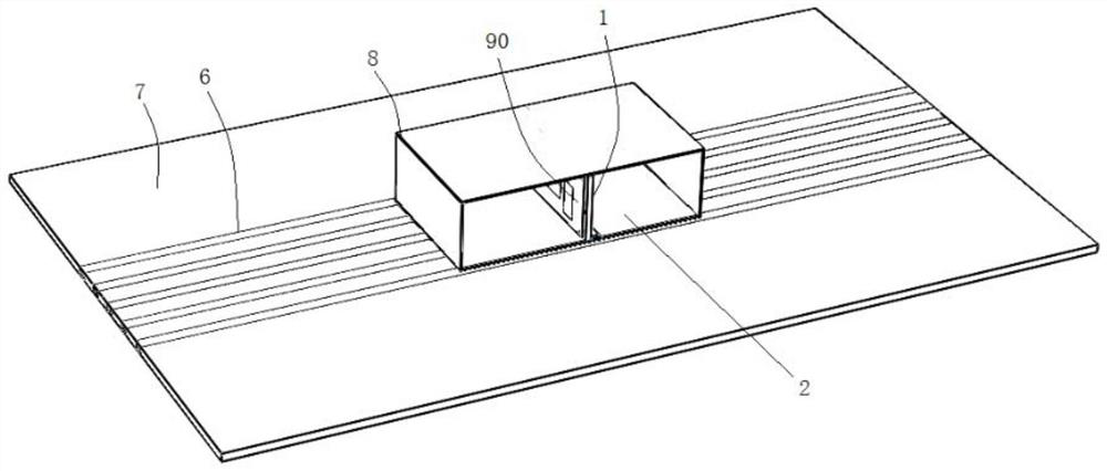
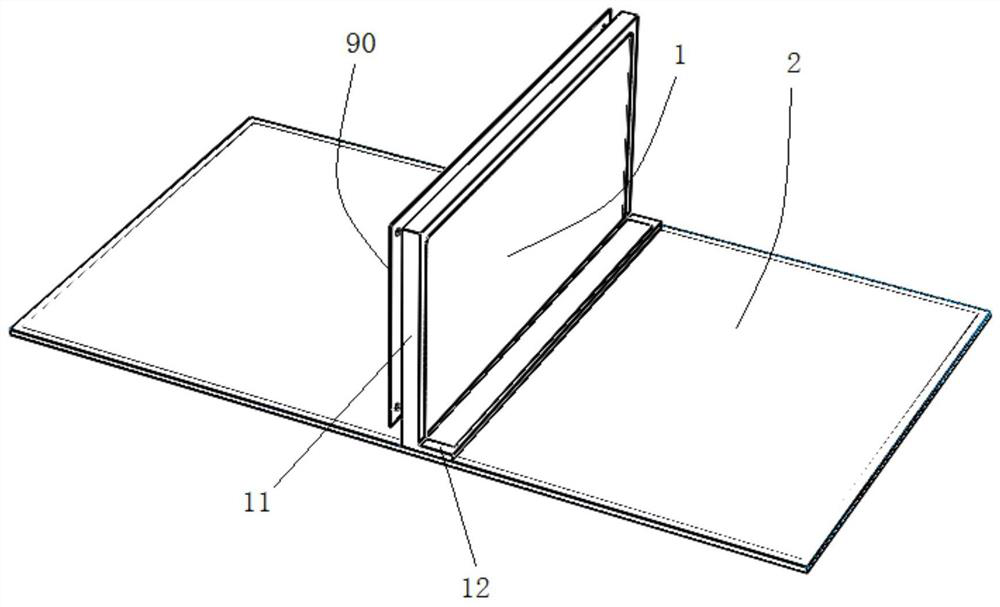
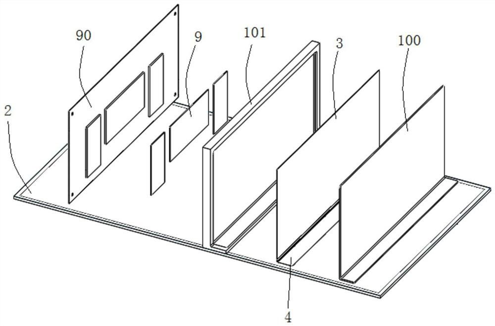

Image

  • Heat dissipation device and electronic equipment with same
  • Heat dissipation device and electronic equipment with same
  • Heat dissipation device and electronic equipment with same

Examples


Embodiment Construction

[0040] Various exemplary embodiments of the present invention will now be described in detail with reference to the accompanying drawings. It should be noted that the relative arrangements of components and steps, numerical expressions and numerical values ​​set forth in these embodiments do not limit the scope of the present invention unless specifically stated otherwise.

[0041] The following description of at least one exemplary embodiment is merely illustrative in nature and in no way taken as limiting the invention, its application or uses.

[0042] Techniques and devices known to those of ordinary skill in the relevant art may not be discussed in detail, but where appropriate, such techniques and devices should be considered part of the description.

[0043] In all examples shown and discussed herein, any specific values ​​should be construed as exemplary only, and not as limitations. Therefore, other instances of the exemplary embodiment may have different values.

...


PUM


Abstract

The invention discloses a heat dissipation device and electronic equipment with the heat dissipation device. The heat dissipation device comprises a first base body with an inner accommodating cavity,and a second base body with an accommodating cavity, wherein the first base body comprises a cooling part corresponding to a heat source and a connecting part combined and fixed on the second base body; and the inner accommodating cavity comprises a first chamber corresponding to the cooling part and a second chamber corresponding to the connecting part, and the first chamber and the second chamber communicate with each other to form the inner accommodating cavity. The heat dissipation device further comprises: a first capillary core component fixed in the first chamber; a second capillary core component fixed in the second chamber; and a third capillary core component fixed in the accommodating cavity of the second base body, wherein the opposite adjacent ends of the first capillary corecomponent and the second capillary core component are connected and communicate with each other, and the inner accommodating cavity and the accommodating cavity are each filled with a cooling workingmedium. Efficient heat transfer and soaking of a case structure serving as the heat source in different spatial directions are achieved.

Description

technical field [0001] The invention relates to the technical field of heat dissipation. More specifically, it relates to a heat dissipation device and electronic equipment with the heat dissipation device. Background technique [0002] In the space application environment, there is no air convection, and thermal control design can only rely on heat conduction and radiation. Traditional ground fans cannot play a role in space applications. The liquid cooling system has a high heat dissipation capacity, but its system is relatively complex, and its reliability often cannot meet its life requirements in a space environment, and its weight is relatively large. Based on the fact that the integration of space electronic equipment is getting higher and higher, the heat flux density of chips is getting bigger and bigger, the space layout is getting more and more compact, and some equipment has more and more strict requirements on temperature uniformity. High performance, light we...

Claims


Application Information

Patent Timeline
Patent Type & Authority Applications(China)
IPC IPC(8): H05K7/20
CPCH05K7/20309H05K7/20318H05K7/20336
Inventor 于印赵益涛李子轩李璨随愿愿段友东
Owner 航天科工空间工程发展有限公司
Learn More