
Novel automatic assembling equipment for power supply socket

An automatic assembly and socket technology, which is applied in the assembly/disassembly of contact parts, can solve the problem of single function, and achieve the effects of labor saving, stable operation and high assembly efficiency

Pending Publication Date: 2020-12-11
SUZHOU E CONN TECH
View PDF0 Cites 3 Cited by
  • Summary
  • Abstract
  • Description
  • Claims
  • Application Information

AI Technical Summary

Problems solved by technology

[0002] The DC JACK product, that is, the power interface, is now used more and more widely, and the amount of use is also increasing. The market has higher and higher requirements for production capacity and quality. In this case, vigorously develop automation equipment to meet the demand and reduce labor costs. , and update the original equipment. The power interface is composed of rubber core, terminal, iron shell, and rear plug. The cores are discharged from the end relative to each other. In the subsequent installation station, the rubber core needs to be aligned with the assembly station. Ordinary direct vibration feeding cannot meet the above requirements. In addition, the installation of the rear plug and the insertion and riveting of the rubber core iron shell , testing, and finished product screening, the existing equipment has a single function and needs multiple equipment to be used together to complete it. Based on the above defects and deficiencies, it is necessary to improve the existing technology and design a new type of automatic assembly equipment for power sockets

Method used


Image

  • Novel automatic assembling equipment for power supply socket
  • Novel automatic assembling equipment for power supply socket
  • Novel automatic assembling equipment for power supply socket

Examples


Embodiment Construction

[0030]The preferred embodiments of the present invention will be described in detail below in conjunction with the accompanying drawings, so that the advantages and features of the invention can be more easily understood by those skilled in the art, so as to define the protection scope of the present invention more clearly.

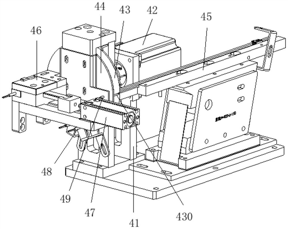
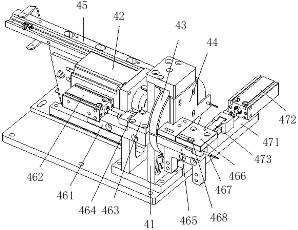
[0031] see Figure 1 to Figure 10 , the embodiment of the present invention includes:

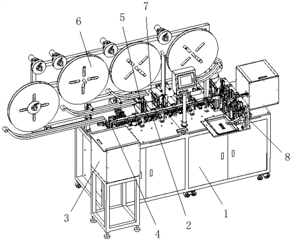
[0032] A new type of automatic assembly equipment for power sockets. The new automatic assembly equipment for power sockets includes a frame 1, a linear processing flow channel 2, a rubber core vibrating plate 3, a rotating material turning and dislocation mechanism 4, a pin insertion mechanism 5, and a terminal discharging device. 6. The sweeping belt structure 7 and the assembly testing mechanism 8, the frame 1 is provided with a linear processing flow channel 2, the left side of the linear processing flow channel 2 is provided with a rubber core vibrating plate 3, a...


PUM


Abstract

The invention discloses novel automatic assembling equipment for a power supply socket. The novel automatic assembling equipment comprises a rack, a linear machining flow channel, a rubber core vibration disc, a rotary overturning and staggering mechanism, a pin mechanism, a terminal discharging device, material sweeping belt structures and an assembling and testing mechanism, wherein the linear machining flow channel is arranged on the rack; the rubber core vibration disc is arranged on the left side of the linear machining flow channel and is conveyed to the linear machining flow channel through the rotary overturning and staggering mechanism; the pin mechanism is arranged on the rear side of the linear machining flow channel and comprises a positive terminal, a center pin and a negativeterminal pin; the terminal discharging device in butt joint with the rear side terminal of the pin mechanism is arranged on the rear side terminal; the next station of each terminal pin is provided with one material sweeping belt structure; and the right side of the linear processing flow channel is provided with the assembling and testing mechanism in a butt joint manner. By means of the mode, the novel automatic assembling equipment is compact in structure, stable in operation, capable of automatically assembling, detecting and classifying power sockets and high in assembling efficiency.

Description

technical field [0001] The invention relates to the technical field of connector production, in particular to a novel power socket automatic assembly equipment. Background technique [0002] The DC JACK product, that is, the power interface, is now used more and more widely, and the amount of use is also increasing. The market has higher and higher requirements for production capacity and quality. In this case, vigorously develop automation equipment to meet the demand and reduce labor costs. , and update the original equipment. The power interface is composed of rubber core, terminal, iron shell, and rear plug. The cores are discharged from the end relative to each other. In the subsequent installation station, the rubber core needs to be aligned with the assembly station. Ordinary direct vibration feeding cannot meet the above requirements. In addition, the installation of the rear plug and the insertion and riveting of the rubber core iron shell , testing and product scr...

Claims


Application Information

Patent Timeline
IPC IPC(8): H01R43/20
CPCH01R43/20
Inventor 王发帅肖亮侯耀岭廖承千
Owner SUZHOU E CONN TECH
Learn More