
Fuel assembly with helical fuel rods

A technology of fuel assembly and helical structure, which is applied in the field of nuclear power, can solve the problems that small nuclear power plants are not suitable, the fuel assembly structure is complicated, and the processing and manufacturing are difficult, and achieve the effects of avoiding abrasion failure, simple structure, and convenient processing and manufacturing

Active Publication Date: 2021-09-07
LINGDONG NUCLEAR POWER +3
View PDF13 Cites 0 Cited by
  • Summary
  • Abstract
  • Description
  • Claims
  • Application Information

AI Technical Summary

Problems solved by technology

[0004] The fuel assembly is complex in structure and difficult to process and manufacture, and is more suitable for large pressurized water reactors, but not suitable for small nuclear power plants for special purposes;
[0005] The contact between the fuel rod and the grid in the fuel assembly has strong flow-induced vibration and abrasion under the action of the coolant, which easily induces fuel rod abrasion failure;
[0006] The fuel assembly is equipped with a multi-layer grid along the axial direction, which promotes the mixing of the coolant, but the mixing effect at the downstream of the grid gradually weakens with the increase of the distance, which may still cause local overheating of the fuel rods;
[0007] The fuel assembly has several guide tubes radially arranged to accommodate the action of the control rods to control the reactivity, but there is still a problem of insufficient reactivity control for some fuel rods far away from the control rods

Method used


Image

  • Fuel assembly with helical fuel rods
  • Fuel assembly with helical fuel rods
  • Fuel assembly with helical fuel rods

Examples


Embodiment Construction

[0043] In order to have a clearer understanding of the technical features, purposes and effects of the present invention, the specific implementation manners of the present invention will now be described in detail with reference to the accompanying drawings. In the following description, it should be understood that "front", "rear", "upper", "lower", "left", "right", "longitudinal", "horizontal", "vertical", "horizontal", The orientation or positional relationship indicated by "top", "bottom", "inner", "outer", "head", "tail", etc. is based on the orientation or positional relationship shown in the drawings, and is constructed and operated in a specific orientation, It is only for the convenience of describing the technical solution, but does not indicate that the referred device or element must have a specific orientation, so it should not be construed as a limitation of the present invention.

[0044] It should also be noted that terms such as "installation", "connection", ...


PUM


Abstract

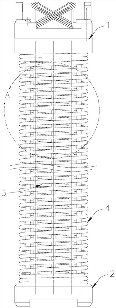
The invention relates to a fuel assembly with a fuel rod in a spiral structure, comprising an upper tube base, a lower tube base, and a fuel rod element installed between the upper tube base and the lower tube base; the fuel rod The element includes a first fuel rod and a second fuel rod in a spiral structure, and the second fuel rod is arranged on the outer periphery of the first fuel rod. The fuel assembly with helical fuel rods has a simple structure and is easy to process and manufacture; there is no structural grid, which avoids hooking between fuel assemblies during hoisting; no grid, avoids vibration and abrasion between fuel rods and grids, Avoid fuel rod abrasion failure; the fuel rod adopts a spiral structure, which improves the lateral flow of coolant, accelerates mixing, and optimizes heat transfer performance.

Description

technical field [0001] The invention relates to the technical field of nuclear power, in particular to a fuel assembly with a spiral fuel rod. Background technique [0002] The typical fuel assemblies currently used in commercial reactors have stable structures and high heating power, but they have many components and complex manufacturing processes, especially in the high-temperature, high-pressure, and strong-radiation environment of the reactor. There are compatibility problems between structural components. This fuel design is more suitable for high-power commercial reactors, but it is not suitable for small nuclear power plants for special purposes (such as deep sea, aerospace, etc.). Small nuclear power plants focus on safety, flexibility, and convenience, which requires nuclear fuel to have a simple structure, easy processing and manufacturing, easy installation in nuclear power plants, and adequate reactivity control. [0003] Such as Figure 1-2 As shown, a typical...

Claims


Application Information

Patent Timeline
Patent Type & Authority Patents(China)
IPC IPC(8): G21C3/14G21C3/322
CPCG21C3/14G21C3/322Y02E30/30
Inventor 李长征张利斌曹进林少芳张鹏鹤刘欣李颖虹邓勇军聂立红陈建新
Owner LINGDONG NUCLEAR POWER
Learn More