


Quick Research
Generate reliable direction feasibility study reports for your R&D in just a few steps.

Technical Q&A
Discover and master advanced knowledge NOW. Basics, ideas, possibilities, all at once.

Find Solutions
As an expert in R&D theories, this can generate solutions to your technical problems instantly.

Evaluate Feasibility
Analyze your overall solution with one click, know your potential R&D risks in advance.

Monitor Landscape
Get weekly tech updates, stay abreast of the latest tech innovations and key insights.
Method and device for predicting CO2 miscible flooding effected oil well gas channeling time of low-permeability reservoir
A time prediction, miscible flooding technology, applied in wellbore/well components, earthwork drilling, climate sustainability, etc. precise effect
- Summary
- Abstract
- Description
- Claims
- Application Information
AI Technical Summary
Problems solved by technology
Method used
Image

Examples
Embodiment 1
[0076] Example 1; A low-permeability reservoir CO 2 A method for predicting gas channeling time of a miscible flooding effective oil well, the prediction method includes the following steps:
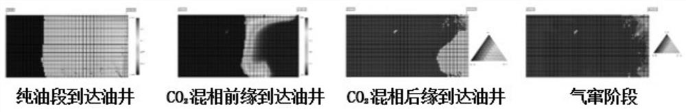
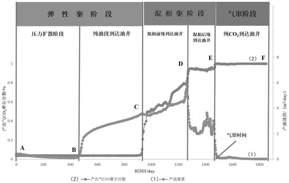
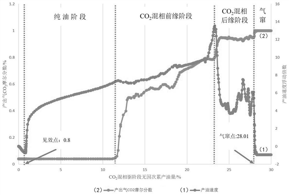
[0077] S10: Use CMG numerical simulation software to simulate to obtain an oil field model, the parameters of the oil field model include the oil production rate of the oil well and the CO in the produced gas. 2 The mole fraction of the oil well is used to analyze the oil production rate and the CO in the produced gas 2 The corresponding relationship between the two mole fractions and the fluid flow stage of each reservoir;
[0078] In the specific implementation, the CMG numerical simulation software was used to simulate an oil well in the G69 block, and the following results were obtained: figure 1 Schematic diagram of the different flow stages of a G69 well model shown. And through the simulation of the oil production rate of a certain oil well in block G69 and the mole fraction of...
Embodiment 2
[0119] Example 2; A low permeability oil reservoir CO 2 A device for predicting gas channeling time in miscible flooded wells, based on a CO 2 A method for predicting the gas breakthrough time of a miscible flooding-effective oil well is provided with a computer device, which includes a storage and a high-speed processor.
[0120] A computer program is stored in the storage, and the computer program comprises an effective oil well dynamic analysis module 1, an effective oil well gas channeling early warning module 2, a gas channeling time influencing factor analysis module 3, a gas channeling time prediction model training module 4 and Development well gas channeling time prediction module 5.
[0121] Effective oil well performance analysis module 1 analyzes the production performance of effective oil wells, and divides low permeability oil reservoirs into CO according to the limit thresholds of indicators such as oil production rate and CO2 mole fraction in produced gas. 2 ...
PUM
 Abstract
Description
Claims
Application Information
 - R&D Engineer
- R&D Manager
- IP Professional
- Industry Leading Data Capabilities
- Powerful AI technology
- Patent DNA Extraction
Browse by: Latest US Patents, China's latest patents, Technical Efficacy Thesaurus, Application Domain, Technology Topic, Popular Technical Reports.
© 2024 PatSnap. All rights reserved.Legal|Privacy policy|Modern Slavery Act Transparency Statement|Sitemap|About US| Contact US: help@patsnap.com