Push-pull type anti-reverse-spraying excrement collecting device

An anti-backblow, push-pull technology, applied in the direction of transportation and packaging, vehicle sanitary equipment, sanitary equipment, etc., can solve the problem of easy leakage of large dirty tanks and valve bodies, increased gas consumption, electricity consumption, and weight of toilet collection devices Large and other problems, to achieve the effect of anti-blowback, simplified structure, good sealing performance

Active Publication Date: 2020-12-11
ZHUZHOU CSR TIMES ELECTRIC CO LTD
View PDF5 Cites 0 Cited by
  • Summary
  • Abstract
  • Description
  • Claims
  • Application Information

AI Technical Summary

Problems solved by technology

In actual use, when the control valve between the toilet and the transfer box fails to be closed for sealing, if the system performs the positive pressure transfer operation of the dirt at the same time, the residual dirt in the pipeline may be sprayed back from the toilet, thereby affecting Toilets cause pollution and even cause harm to users
Some vacuum-maintaining feces collection systems have canceled the transfer box, but the large dirty tank of this kind of feces collection device needs to maintain a negative pressure state, resulting in thicker panels of the large dirty tank and high sealing requirements, which in turn leads to the leakage of the feces collection device. Heavy weight and high cost. In addition, the large dirty tank and valve body are prone to leakage, which increases gas and electricity consumption, which is not conducive to energy saving

Method used


Image

  • Push-pull type anti-reverse-spraying excrement collecting device
  • Push-pull type anti-reverse-spraying excrement collecting device

Examples


Embodiment Construction

[0018] Embodiments of the present invention are described in detail below, examples of which are shown in the drawings, wherein the same or similar reference numerals designate the same or similar elements or elements having the same or similar functions throughout. The embodiments described below by referring to the figures are exemplary only for explaining the present invention and should not be construed as limiting the present invention.

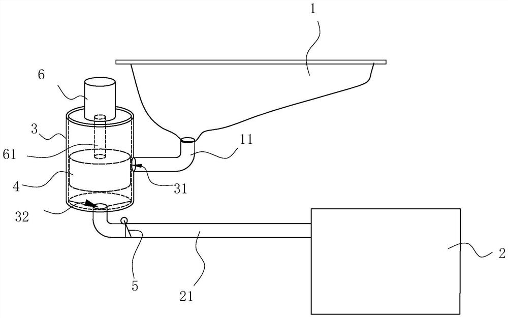
[0019] Such as figure 1 It is a structural schematic diagram of the stool collection device of the present application. As shown in the figure, this kind of push-pull anti-spray anti-spray collection device includes a toilet 1 and a large sewage tank 2. The lower end of the toilet 1 is connected with a sewage inlet pipe 11, and the upper end of the large sewage tank 2 Connected with a sewage pipe 21, it also includes a cylinder 3, a piston 4 that is arranged in the cylinder 3 and seals the cavity of the cylinder 3, a drive mechanism that...


PUM


Abstract

The invention relates to a push-pull type anti-reverse-spraying excrement collecting device. The device comprises a toilet stool, a large sewage tank, a cylinder body, a piston arranged in the cylinder body and sealing a cavity of the cylinder body, a driving mechanism capable of driving the piston to move in the axial direction of the cylinder body, and a one-way valve arranged in a sewage discharge pipe, wherein a sewage inlet pipe is connected to the lower end of the toilet stool; the sewage discharge pipe is connected with the large sewage tank; one end of the cylinder body is provided with a sewage outlet connected with the sewage discharge pipe, and the side wall of the cylinder body is provided with a sewage inlet connected with the sewage inlet pipe; and the piston closes the sewage inlet when the excrement collecting device does not work and moves towards the other end of the cylinder body firstly during sewage discharging so that negative pressure can be formed in the cavityclose to the sewage outlet and the sewage inlet pipe can be communicated to suck in sewage in the toilet stool, and then the piston moves towards one end of cylinder body so that positive pressure canbe formed in the cavity close to the sewage outlet and the one-way valve can be opened to enable the sewage in the cavity to enter the large sewage tank. The excrement collecting device is simple andreliable in structure and beneficial to saving production and use cost, and has a good anti-reverse-spraying effect.

Description

technical field [0001] The invention relates to the technical field of feces collection devices, in particular to a push-pull anti-spray anti-spray feces collection device on rail passenger cars or aircrafts. Background technique [0002] The feces collection device is an essential waste disposal system on trains, airplanes and even long-distance buses. The defecation collection device in the prior art mainly uses a vacuum generator to generate negative pressure in the transfer box to remove the waste in the toilet. Then the dirt in the transfer box is transferred to the big dirt box by positive pressure. The stool collection device uses valve parts at the front and rear ends of the transfer box to control the opening and closing of the pipeline so as to realize the adjustment of the pressure in the transfer box. In actual use, when the control valve between the toilet and the transfer box fails to be closed for sealing, if the system performs the positive pressure transfer...

Claims


Application Information

Patent Timeline
Patent Type & Authority Applications(China)
IPC IPC(8): B61D35/00B64D11/02B60R15/04
CPCB60R15/04B61D35/007B64D11/02
Inventor 陈大伟单安兵
Owner ZHUZHOU CSR TIMES ELECTRIC CO LTD
Why Eureka
Try Eureka