Lamp
A technology of lamps and lamp holders, which is applied in the field of lighting, can solve the problems of high cost, heavy volume, and large volume, and achieve the effects of reducing the risk of damage, wide lighting range, and small overall volume
- Summary
- Abstract
- Description
- Claims
- Application Information
AI Technical Summary
Problems solved by technology
Method used
Image

Examples
Embodiment 1
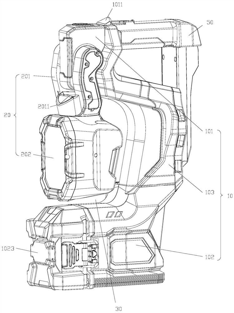
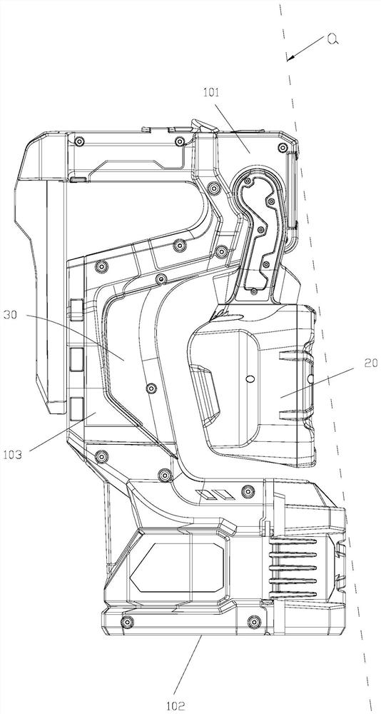
[0038] see figure 1 , the present invention provides a lamp, including a lamp body 10 , a lamp cap assembly 20 and a damper 40 . Wherein, the lamp body 10 includes a lamp cap fixing part 101, a base 102, and a lamp body 103 connecting the lamp cap fixing part 101 and the base 102, and the same side of the base 102 and the lamp cap fixing part 101 partly extends out of the lamp body 103 to form the lamp body 103. The housing cavity 30, the lamp cap assembly 20 includes a bracket 201 and a lamp cap 202, the lamp cap 202 is rotatably connected to the bracket 201 and can rotate around its own central axis, the bracket 201 is rotatably connected to the lamp cap fixing part 101, and the bracket 201 can drive the lamp cap 202 relative to The lamp cap fixing part 101 is from the inside of the receiving cavity 30 to the top of the lamp cap fixing part 101 ( Figure 5 As the lamp cap 202 rotates to the top of the lamp cap fixing part 101 ), the damper 40 is arranged at the joint betwe...
Embodiment 2
[0044] On the basis of the first embodiment, further, the rotation angle of the bracket 201 relative to the lamp head fixing part 101 is greater than or equal to 180°. In this way, it can ensure that the bracket 201 drives the lamp head 202 to rotate above the lamp head fixing part 101 , so that the lamp head 202 can realize illumination on the rear hemisphere of the space.
[0045] see figure 1 , further, the bracket 201 is provided with a first supporting portion 2011, and the top of the lamp cap fixing portion 101 is provided with a second supporting portion 1011, when the bracket 201 rotates to the top of the lamp cap fixing portion 101 (see Figure 5 ), the first support portion 2011 abuts against the second support portion 1011 . In this way, all the weight of the lamp cap 202 can be transmitted to the lamp body 10 by the first supporting part 2011 and the second supporting part 1011, avoiding direct force damage to the connection between the bracket 201 and the lamp c...
Embodiment 3
[0047] On the basis of Embodiment 1 or Embodiment 2, further, the lamp cap 202 rotates along its own axis in two opposite directions, so as to avoid the continuous rotation of the lamp cap 202 around its own axis in the same direction and cause the wires of the light-emitting elements in the lamp cap 202 to A twisting phenomenon occurs, wherein the lamp head 202 rotates at least 180° to one side, so as to ensure that the lamp head 202 can turn the lighting direction to the rear hemisphere of the space, so as to realize the rotating illumination of the rear hemisphere of the space.
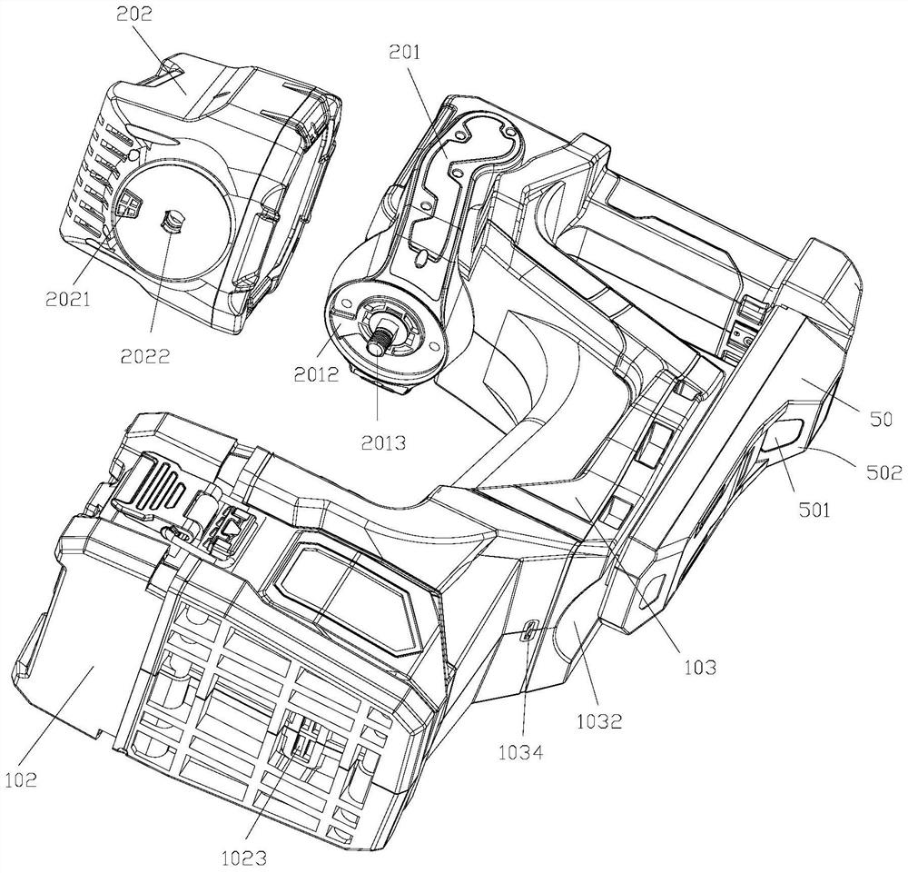
[0048] see figure 2 Specifically, the bracket 201 is provided with a rotating shaft 2013, and the middle part of the lamp holder 202 is provided with a mounting hole 2022 that cooperates with the rotating shaft 2013, and the rotating shaft 2013 is fixed with the mounting hole 2022. Angle, a damping device can be set in the mounting hole 2022, the damping device includes mutually rotatable gaskets ...
PUM
 Abstract
Description
Claims
Application Information
 - R&D
- Intellectual Property
- Life Sciences
- Materials
- Tech Scout
- Unparalleled Data Quality
- Higher Quality Content
- 60% Fewer Hallucinations
Browse by: Latest US Patents, China's latest patents, Technical Efficacy Thesaurus, Application Domain, Technology Topic, Popular Technical Reports.
© 2025 PatSnap. All rights reserved.Legal|Privacy policy|Modern Slavery Act Transparency Statement|Sitemap|About US| Contact US: help@patsnap.com