Control and signaling device or signaling device with luminous element

A signal device and light-emitting element technology, which is applied in the field of signal devices, instructions and signal devices, can solve problems such as short life

Inactive Publication Date: 2003-09-03
KLOCKNER-MOELLER GMBH
View PDF1 Cites 0 Cited by
  • Summary
  • Abstract
  • Description
  • Claims
  • Application Information

AI Technical Summary

Problems solved by technology

Of course, incandescent lamps have disadvantages, that is, their lifespan is relatively short compared with other illuminants (such as light-emitting diodes)

Method used


Image

  • Control and signaling device or signaling device with luminous element
  • Control and signaling device or signaling device with luminous element
  • Control and signaling device or signaling device with luminous element

Examples


Embodiment Construction

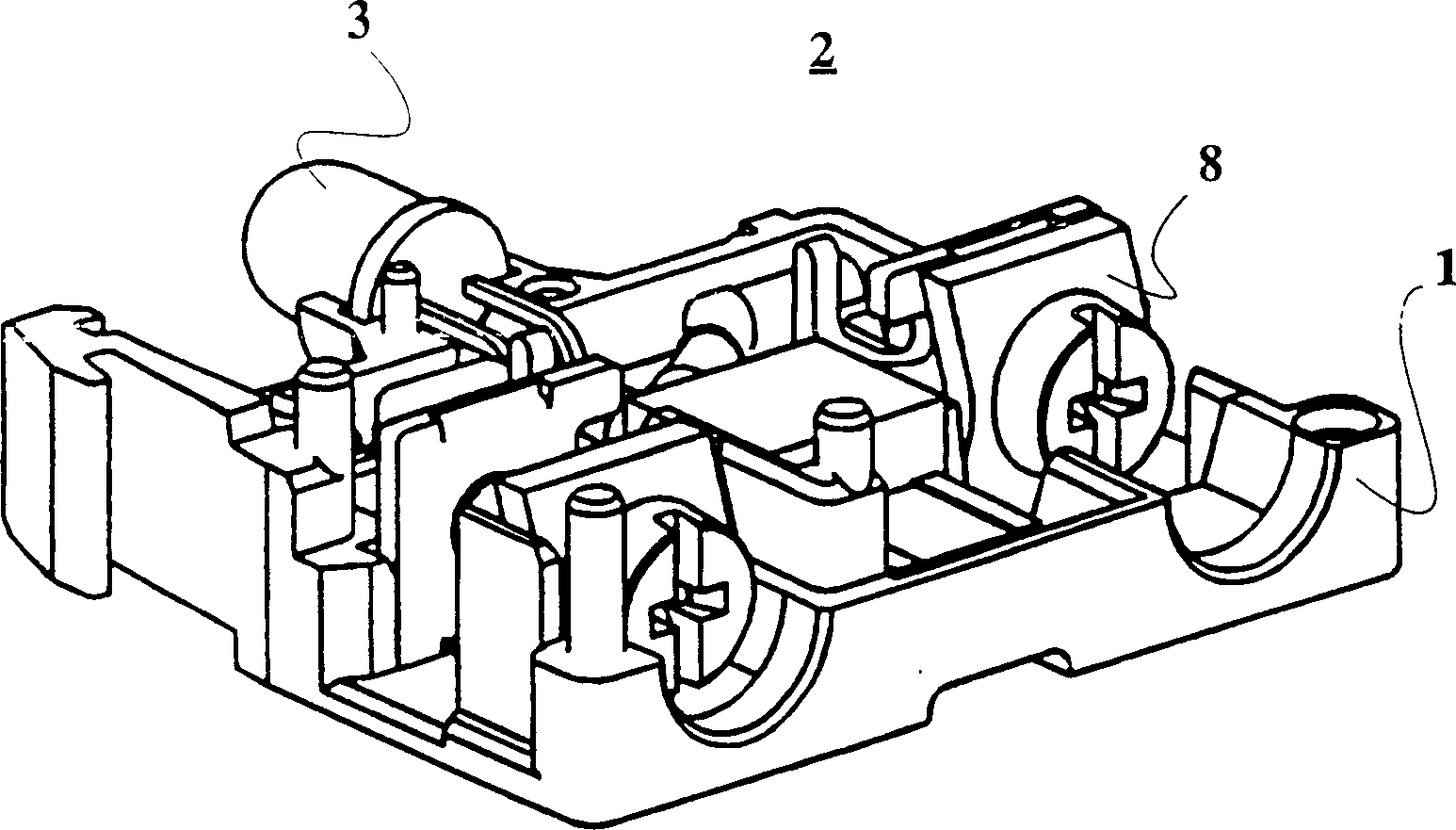
[0021] figure 1 The housing half 1 of the functional part 2 with a light-emitting diode 3 is shown in . The command and signaling device, not fully shown, which can be an illuminated pushbutton, or which can be a signal light, is equipped with a light-emitting element and consists of a front part and a fixed adapter, the functional part 2 can be snapped onto it.

[0022] According to the present invention, only the light-emitting diode 3 with the light-emitting diode head 5 and the connecting wire 4 is combined on the functional part 2, wherein the light-emitting diode head 5 is embedded in the receptacle 6 and fixed, and the radiation of the light-emitting diode 3 The angle is 30-45 degrees, and the luminous intensity of the LED 3 is at least 0.5 candela.

[0023] Since the radiation angle is 30-45 degrees, the light beams are focused on the inner surface of the LED head, making the LED head appear particularly bright. Due to the use of light-emitting diodes 3 with a lumin...


PUM


Abstract

A control and signaling unit or a signaling unit having a light-emitting element, made up of a front element and a mounting adapter for locking the functional elements into place. This is achieved in that only one light-emitting diode having a diode crown and connecting wires are integrated in the functional element, the diode crown being embedded and retained in a receptacle, the light-emitting diode having an angle of radiation of 30-45°. The light-emitting diode has a luminosity of at least 0.5 candela, and an electronic circuit is arranged on circuit conductors, secured to the inner housing wall of a housing half and applied using a foil heat-embossing process.

Description

technical field [0001] The invention relates to a command and signaling device or a signaling device. Background technique [0002] In DE29800780 a functional part for a signaling device with luminous elements is shown and described, wherein the signaling device consists of a front part and a fastening adapter on which the functional part can be locked . [0003] The functional part has a light with a latch-like support. The illuminant uses an incandescent lamp. Of course, incandescent lamps have the disadvantage that their lifetime is relatively short compared to other illuminants such as light-emitting diodes. The insulating material housing has printed wiring. As described in DE 29800780, the printed circuit is applied by means of a MID-technical production method (two-component injection molding). [0004] It is also known to apply the printed circuit by means of hot pressing, as shown in the company brochure of the 3D MID Research Association in "Three-dimensional ...

Claims


Application Information

Patent Timeline
Patent Type & Authority Patents(China)
IPC IPC(8): F21S8/00H05K1/00H05K1/18H05K3/04H05K3/30
CPCY10S362/80H05K3/046H05K1/18H05K2201/10106H05K3/301H05K1/0284F21W2111/00H05K2201/10446H05K2201/0999
Inventor 贝恩德·沃尔夫约尔格·舍费尔于尔根·福尔贝格于尔根·赫格纳
Owner KLOCKNER-MOELLER GMBH
Why Eureka
Try Eureka