A flipping thin steel plate folding machine
A technology of thin steel plate and edge folding machine, which is applied in the direction of feeding device, manufacturing tools, and pushing out equipment, etc. It can solve the problems of low work efficiency, cumbersome operation steps, and heavy workload of thin steel plate edge folding, and achieves convenient collection and improved Work efficiency and workload reduction effects
- Summary
- Abstract
- Description
- Claims
- Application Information
AI Technical Summary
Problems solved by technology
Method used
Image

Examples
Embodiment 1
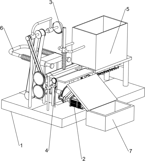
[0023] A flip-type thin steel plate folding machine, such as figure 1 As shown, it includes a bottom plate 1, a motor 2, a pressure plate mechanism 3, a bending mechanism 4, a feeding mechanism 5 and a collection box 7. The top front side of the bottom plate 1 is provided with a motor 2, and the left side of the bottom plate 1 is provided with a pressure plate mechanism on the back side of the top 3. The platen mechanism 3 is connected to the output shaft of the motor 2. A bending mechanism 4 is provided on the front side of the top left of the bottom plate 1, a feeding mechanism 5 is provided on the right side of the top of the bottom plate 1, and a collection box 7 is placed on the front side of the bottom plate 1.
[0024] When people need to fold the thin steel plate, people first place the thin steel plate on the components of the feeding mechanism 5, and then start the motor 2, and the components of the motor 2 rotate to drive the components of the pressing plate mechanis...
Embodiment 2
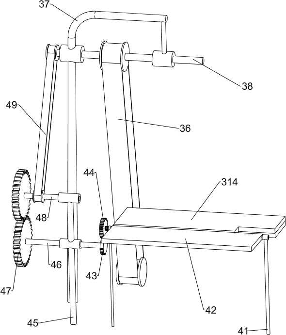
[0026] On the basis of Example 1, as Figure 2-4 As shown, the platen mechanism 3 includes a pinion gear 31, a large gear 32, a short fixed sleeve 33, a No. No. transmission shaft 38, large missing gear 39, rack 310, fixed connecting rod 311, pressure spring 312, long plate 313, worktable 314 and support column 315, the rear of the output shaft of motor 2 is provided with a pinion 31, the bottom plate 1. The left middle of the top and the bottom side of the bottom 1 are provided with short fixed sleeves 33. The tops of the short fixed sleeves 33 are rotatably connected with a No. There is a large gear 32, the large gear 32 meshes with the pinion 31, a bevel gear combination 35 is connected between the A-number transmission shaft 34, the top left end of the bottom plate 1 is provided with a long rod double sleeve 37, and the long rod double sleeve 37 is on the A No. B transmission shaft 38 is rotatably connected on the side, a first belt transmission device 36 is connected bet...
Embodiment 3
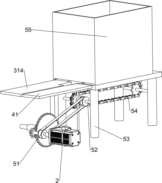
[0031] On the basis of Example 2, as Figure 5-7 As shown, the feeding mechanism 5 includes a third belt transmission device 51, a No. E transmission shaft 52, a bracket 53, a chain transmission device 54, a discharging box 55 and a push plate 56. Bracket 53, a No. E transmission shaft 52 is rotatably connected between the brackets 53, a third belt transmission device 51 is connected between the left No. E transmission shaft 52 and the output shaft of the motor 2, and a No. E transmission shaft 52 is connected There is a chain transmission device 54 , a discharge box 55 is arranged on the top of the bracket 53 , and a push plate 56 is arranged on the chain transmission device 54 .
[0032] When people need to push the thin steel plate onto the workbench 314, they first place the thin steel plate in the discharge box 55. With the cooperation of the motor 2 and the platen mechanism 3, the gap between the long plate 313 and the workbench 314 increases. The rotation of the output...
PUM
 Abstract
Description
Claims
Application Information
 - R&D
- Intellectual Property
- Life Sciences
- Materials
- Tech Scout
- Unparalleled Data Quality
- Higher Quality Content
- 60% Fewer Hallucinations
Browse by: Latest US Patents, China's latest patents, Technical Efficacy Thesaurus, Application Domain, Technology Topic, Popular Technical Reports.
© 2025 PatSnap. All rights reserved.Legal|Privacy policy|Modern Slavery Act Transparency Statement|Sitemap|About US| Contact US: help@patsnap.com