


Quick Research
Generate reliable direction feasibility study reports for your R&D in just a few steps.

Technical Q&A
Discover and master advanced knowledge NOW. Basics, ideas, possibilities, all at once.

Find Solutions
As an expert in R&D theories, this can generate solutions to your technical problems instantly.

Evaluate Feasibility
Analyze your overall solution with one click, know your potential R&D risks in advance.

Monitor Landscape
Get weekly tech updates, stay abreast of the latest tech innovations and key insights.
Construction waste treatment equipment
A technology for construction waste and equipment, applied in the field of construction waste treatment equipment, can solve the problems of no garbage blocking and dust removal, garbage sliding, large dust in the workplace, and cross-flow of sewage, etc., and achieves good dust reduction effect.
- Summary
- Abstract
- Description
- Claims
- Application Information
AI Technical Summary
Problems solved by technology
Method used
Image


Examples
Embodiment 1
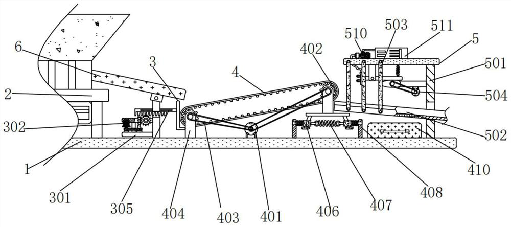
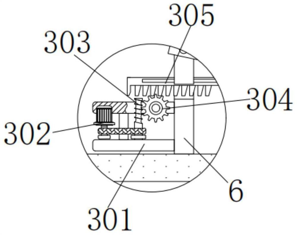
[0042] A construction waste processing equipment, comprising a horizontal plate 1, a crusher 2 and a first blanking plate 6, a crusher 2 is installed on the left side of the upper surface of the horizontal plate 1, the model of the crusher 2 is 800, and the output of the crusher 2 is A first blanking plate 6 is fixedly connected to the opening, and a chute is processed at the middle opening of the first blanking plate 6. The lower surface of the first blanking plate 6 is fixedly connected with the horizontal plate 1. The first blanking plate 6 The bottom left side of the bottom is equipped with a stopper device 3, the stopper device 3 includes an H-shaped plate 301, a first motor 302, a threaded rod 303, a gear 304 and a T-shaped tooth plate 305, and the right side of the H-shaped plate 301 is connected to the first The blanking plate 6 is fixedly connected, the width of the bottom of the H-shaped plate 301 is larger than that of the top, and the left side of the H-shaped plate...
Embodiment 2
[0044] As an option, see figure 1 and 3 -6, construction waste treatment equipment, a transportation device 4 is installed in the middle of the top of the horizontal plate 1, and the transportation device 4 includes a second motor 401, a toothed roller 402, a toothed conveyor belt 403, a first vertical plate 404, a support plate 405, The convex block 406, the first spring 407, the second vertical plate 408, the second spring 409 and the collection box 410, the bottom of the second motor 401 is fixedly connected with the horizontal plate 1, the model of the second motor 401 is BLD-09, the first The output shaft of the second motor 401 is connected with two toothed rollers 402 through belt rotation, and the outer wall of the toothed rollers 402 is meshed with a toothed conveyor belt 403. The toothed conveyor belt 403 includes an upper belt body 41 and a lower belt body 42. The belt body 41 is a mesh structure, and is installed on the outer surface of the lower belt body 42 thro...
Embodiment 3
[0048] As an option, see figure 1 , 5 And 7, construction waste treatment equipment, the upper right side of the horizontal plate 1 is equipped with a dust suppression device 5, the dust suppression device 5 includes an F-shaped plate 501, a second blanking plate 502, a first connecting rod 503, a third motor 504, and a cam 505 , the second connecting rod 506, the third vertical plate 507, the spray pipe 508, the third spring 509, the water pump 510 and the water tank 511, the lower surface of the F-shaped plate 501 is fixedly connected with the horizontal plate 1, the middle of the F-shaped plate 501 and There is an opening on the top, and the gap between the opening of the F-shaped plate 501 is fitted with a second blanking plate 502. A mesh plate is installed on the lower surface of the second blanking plate 502, which can screen the broken construction waste. The front and rear ends of the plate 502 are movably connected with three first connecting rods 503 through the pi...
PUM
 Abstract
Description
Claims
Application Information
 - R&D Engineer
- R&D Manager
- IP Professional
- Industry Leading Data Capabilities
- Powerful AI technology
- Patent DNA Extraction
Browse by: Latest US Patents, China's latest patents, Technical Efficacy Thesaurus, Application Domain, Technology Topic, Popular Technical Reports.
© 2024 PatSnap. All rights reserved.Legal|Privacy policy|Modern Slavery Act Transparency Statement|Sitemap|About US| Contact US: help@patsnap.com