
X-ray imaging device

An imaging device, X-ray technology, applied in the direction of measuring device, image enhancement, image analysis, etc., can solve the problems of correction degradation, excessive moving time, increased exposure, etc., and achieve the effect of suppressing image quality degradation

Inactive Publication Date: 2020-12-04
SHIMADZU SEISAKUSHO LTD
View PDF1 Cites 0 Cited by
  • Summary
  • Abstract
  • Description
  • Claims
  • Application Information

AI Technical Summary

Problems solved by technology

When thermal fluctuations occur in the grating, there is a problem that the imaging conditions will change between the imaging of the subject and the imaging of the calibration image, and deterioration will occur during calibration.
In addition, when shooting while moving the subject by the conventional fringe scanning method, the time for moving the subject becomes redundant, and the overall imaging time increases, which has the disadvantage of increasing the amount of exposure.

Method used


Image

  • X-ray imaging device
  • X-ray imaging device
  • X-ray imaging device

Examples


no. 1 approach

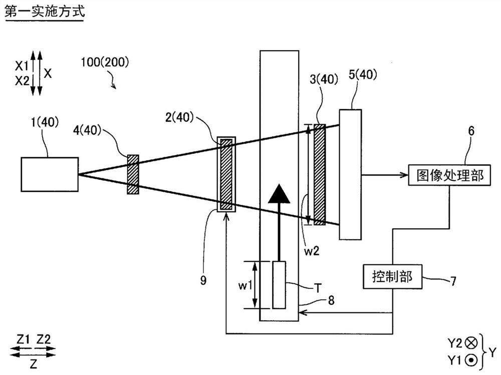
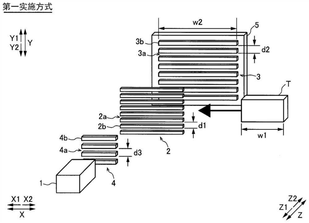
[0049] refer to Figure 1 to Figure 11 The configuration of the X-ray imaging apparatus 100 and the method for generating the phase contrast image 16 by the X-ray imaging apparatus 100 according to the first embodiment of the present invention will be described.

[0050] (Structure of X-ray imaging device)

[0051] First, refer to figure 1 The configuration of the X-ray imaging apparatus 100 according to the first embodiment will be described.

[0052] Such as figure 1 As shown, the X-ray imaging apparatus 100 is an apparatus for imaging the interior of a subject T by utilizing the Talbot effect. The X-ray imaging apparatus 100 can be used for imaging the inside of a subject T which is an object, for example, in a non-destructive inspection application.

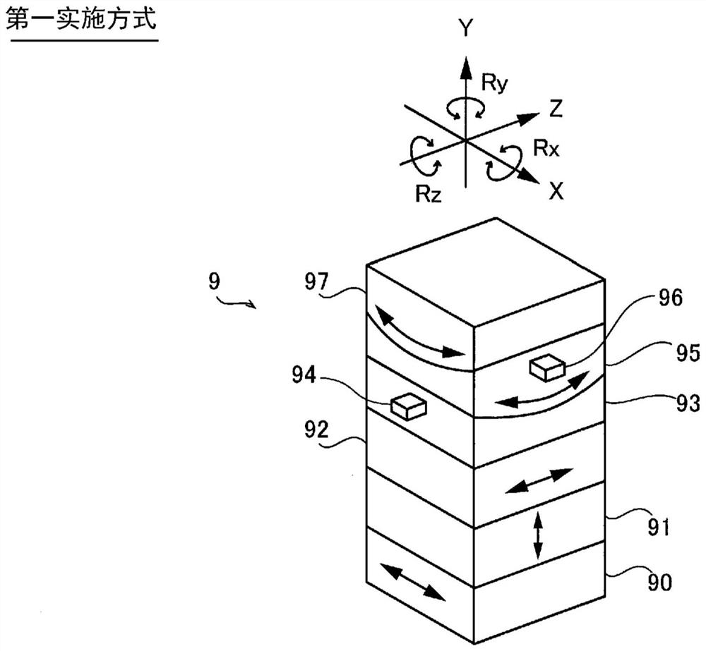
[0053] figure 1 It is a figure which looked at the X-ray imaging apparatus 100 from the Y direction. Such as figure 1 As shown, the X-ray imaging device 100 includes an X-ray source 1, a first grating 2, a second g...

no. 2 approach

[0120] Next, refer to figure 1 with Figure 13 The X-ray imaging apparatus 200 of the second embodiment will be described (see figure 1 ). Unlike the first embodiment in which imaging is performed while moving the subject T to the first to sixth imaging positions, in the second embodiment, the moving mechanism 8 is configured to move the subject T to The body T moves continuously. In addition, the same code|symbol is attached|subjected to the same structure as said 1st Embodiment, and description is abbreviate|omitted.

[0121] (Structure of X-ray imaging device)

[0122] First, refer to figure 1 The structure of the X-ray imaging apparatus 200 of the second embodiment will be described.

[0123] In the second embodiment, the movement mechanism 8 is configured to continuously move the subject T when the subject T is photographed. In addition, the image processing unit 6 is configured to generate a phase contrast image 16 based on the acquired continuous subject image...


PUM


Abstract

An X-ray imaging device (100) is provided with an X-ray source (1), a plurality of gratings, a movement mechanism (8), and an image processing unit (6), the image processing unit (6) being configuredso as to generate a phase contrast image (16) by associating pixel values of pixels of a subject (T) in a plurality of subject images (10) and phase values of moire fringes (30) of the pixels, and matching the positions of pixels in the same position of the subject in the plurality of subject images.

Description

technical field [0001] The present invention relates to an X-ray imaging device, and more particularly to an X-ray imaging device that captures images while moving a subject. Background technique [0002] Conventionally, there is known an X-ray imaging apparatus that captures images while moving a subject. Such an X-ray imaging device is disclosed, for example, in JP-A-2017-44603. [0003] In recent years, there has been a demand for an X-ray imaging device that targets substances such as living body soft tissues and polymer materials. Since the absorption of X-rays by living body soft tissues, polymer materials, etc. is low, it is difficult to obtain images with high contrast in conventional X-ray imaging that performs imaging by contrast based on X-ray absorption. A fringe scanning method is known as a method for imaging living soft tissues, polymer materials, and the like that absorb little X-rays. The fringe scanning method is a method of imaging while shifting an arb...

Claims


Application Information

Patent Timeline
Patent Type & Authority Applications(China)
IPC IPC(8): G01N23/041
CPCG01N23/041G01N2223/1016G01N2223/3301G01N2223/3308G01N2223/32G01N2223/401G01N2223/612G06T7/74G06T7/33G01N23/083G01N2223/303G06T5/50G06T2207/10116G06T2207/30204
Inventor 佐野哲田边晃一木村健士和田幸久德田敏白井太郎土岐贵弘堀场日明森本直树
Owner SHIMADZU SEISAKUSHO LTD
Learn More