Cooling apparatus for cooling a metal material and method for the production and use thereof

A cooling device and material technology, applied in workpiece cooling device, metal rolling, metal rolling, etc., can solve problems such as disadvantage and overcooling of metal materials

Active Publication Date: 2020-12-04
SMS GRP GMBH
View PDF8 Cites 0 Cited by
  • Summary
  • Abstract
  • Description
  • Claims
  • Application Information

AI Technical Summary

Problems solved by technology

In this case, the linear distribution of the coolant disclosed in EP 2 986 400 B1 in the individual width sections of the chilled beam is disadvantageous for the desired greater precision when compensating the predetermined temperature profile
This can especially sometimes lead to an undesired supercooling of the edges of the metal charge

Method used


Image

  • Cooling apparatus for cooling a metal material and method for the production and use thereof
  • Cooling apparatus for cooling a metal material and method for the production and use thereof
  • Cooling apparatus for cooling a metal material and method for the production and use thereof

Examples


Embodiment Construction

[0023] The invention is described in detail below in the form of an exemplary embodiment with the aid of the mentioned figures. In all figures, the same technical elements are provided with the same reference signs.

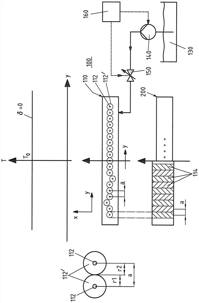
[0024] figure 1 In the middle is shown a cooling device 100 according to the invention for cooling a metal charge 200, as in figure 1 as shown in the lower subfigure of . The cooling device 100 includes at least one cooling beam 110 having a plurality of coolant loading elements 112 . This can be an injection nozzle, a cutout or a U-tube with a corresponding outlet opening for the coolant. exist figure 1 The dots or small circles shown in the chilled beams 110 respectively represent coolant loading elements 112 . The concentric circles around the coolant loading element 112 symbolically represent the corresponding cross section 112' of the outlet opening of the coolant loading element 112. The chilled beams 110 are loaded with coolant by means of a pum...


PUM


Abstract

The invention relates to a cooling apparatus (100) for cooling a metal material and to methods for operating and producing the cooling apparatus. The cooling apparatus has at least one cooling beam (110) having a plurality of coolant application elements (112) for applying a coolant to the metal material, wherein each coolant application element (112) has an outlet opening having a cross-sectionalarea (112') for the outlet of the coolant. In order to be able to adapt such known cooling apparatuses more precisely to different temperature distributions over the width of the metal material to becooled, according to the invention the density of the cross-sectional areas (112') of the outlet openings of the coolant application elements (112) in the width direction y of the cooling beam (110)is adapted and dimensioned in accordance with the magnitude of the slope of the distribution of the temperature T(y) of the metal material over the width of the latter before running in under the cooling beam (110).

Description

technical field [0001] The invention relates to a cooling device for cooling a metal charge, in particular after rolling the metal charge. The invention also relates to a method for operating a cooling device and a method for producing or selecting chilled beams for such a cooling device. Background technique [0002] Such cooling devices and methods for producing and operating cooled beams are known in principle from the prior art. [0003] Thus, WO 2016 / 189903 A1 discloses a binary solution in which supercooling of the metal charge in the edge region is compensated by providing a width shelter at the edge of the metal charge in combination with a coolant collection container. [0004] European patent EP 2 155 411 B1 likewise discloses a solution for reducing inhomogeneous temperature distribution, especially at the edges of the metal mass. Here too, the cover is provided to cover the edge, wherein the cover can however be moved or adjusted in the width direction and also...

Claims


Application Information

Patent Timeline
Patent Type & Authority Applications(China)
IPC IPC(8): B21B45/02B21B37/74
CPCB21B37/74B21B45/0215B21B45/0233B21B2261/21C21D1/667C21D11/005C21D1/60C21D9/46C21D8/0263C21D2221/00
Inventor F·格罗塞·罗德曼
Owner SMS GRP GMBH
Why Eureka
Try Eureka