Zero-crossing detection circuit, pfc circuit and two interleaved parallel pfc circuits
A zero-crossing detection circuit and zero-crossing signal technology, applied in the measurement of current/voltage, measurement of electrical variables, high-efficiency power electronic conversion, etc., can solve the problems of large negative current in the circuit, reducing the reliability of the corresponding system, and low bandwidth Achieve the effect of reducing negative current, compensating distortion and reducing input current harmonics
- Summary
- Abstract
- Description
- Claims
- Application Information
AI Technical Summary
Problems solved by technology
Method used
Image

Examples
Embodiment 1
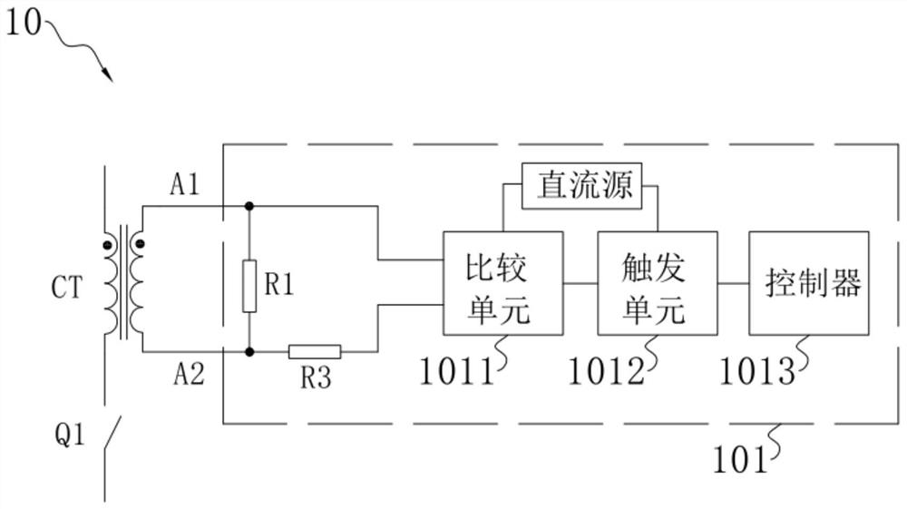
[0039] This embodiment provides a zero-crossing detection circuit, aiming to solve the problem of "it is difficult to accurately determine the zero-crossing for a circuit with freewheeling components". Specifically, refer to figure 1 As shown, the zero-crossing detection circuit 10 includes a current transformer CT, a main switching tube Q1 and a negative current regulation circuit 101 .
[0040]The current transformer CT includes a primary winding and a secondary winding. The primary winding and the main switching tube Q1 are connected in series to form a first converter, and the first converter is cooperatively connected to an AC source. The primary winding has a terminal with the same name and a terminal with the same name. Here, the current flowing from the non-identical terminal of the primary winding to the terminal with the same name is recorded as the forward current of the zero-crossing detection circuit. Otherwise, the current flows from the terminal with the same na...
Embodiment 2
[0051] This embodiment provides a zero-crossing detection circuit, and this embodiment is implemented on the basis of Embodiment 1.
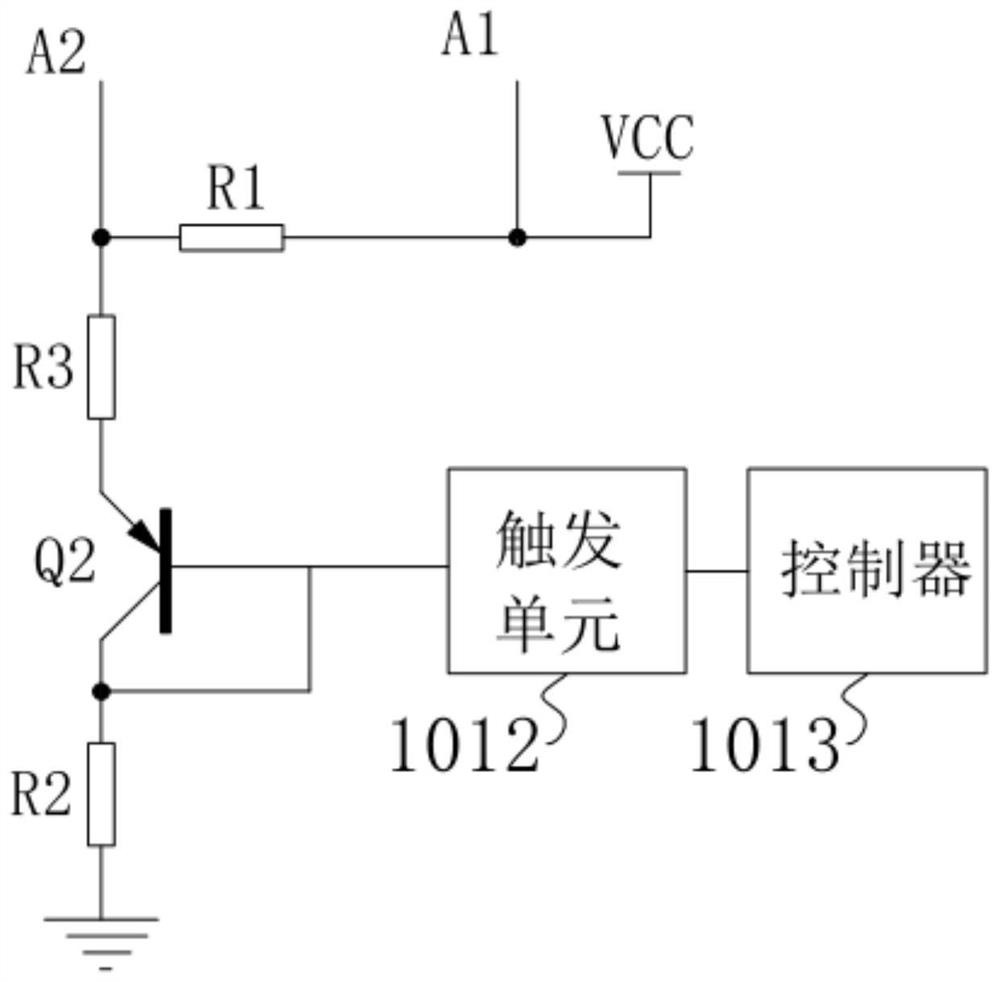
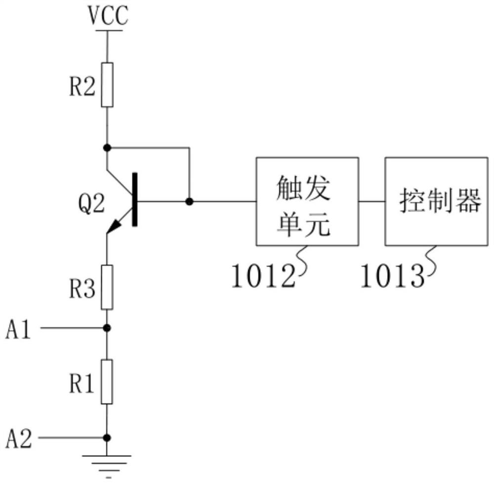
[0052] refer to figure 1 and figure 2 As shown, the comparison unit 1011 may include a comparison switch Q2 and a second resistor R2. Wherein, the first terminal A1 is connected to the DC source, the third resistor R3 is connected in series between the second terminal A2 and the positive terminal of the comparison switch Q2, and the second resistor R2 is connected in series between the ground and the negative terminal of the comparison switch Q2 During this period, the base of the comparison switch Q2 is connected to the negative terminal or grounded through the fifth resistor, and the base of the comparison switch Q2 is connected to the trigger unit 1012 .
[0053] The comparison switch Q2 can be any one of SI MOSFET, IGBT, GaN MOSFET, SIC MOSFET, triode, thyristor and relay, or a bidirectional switch formed by a combination thereof. It is ...
Embodiment 3
[0066] This embodiment provides a PFC circuit with zero-crossing detection, refer to Figure 7 As shown, it includes the zero-crossing detection circuit 10 in Embodiment 1 and / or Embodiment 2 above. Specifically, the PFC circuit with zero-crossing detection includes an AC source, a first diode D1 , a second diode D2 , a first inductor L1 , a capacitor C, a load Rx and two sets of zero-crossing detection circuits 10 . The two groups of zero-crossing detection circuits 10 are respectively denoted as a first zero-crossing detection circuit and a second zero-crossing detection circuit.
[0067] One end of the first inductor L1 is connected to the positive pole of the AC source, and the other end is marked as the connection terminal f. The anode of the first diode D1 and the cathode of the second diode D2 are both connected to the negative pole of the AC source. The detection circuit is cooperatively connected between the connection terminal f and the cathode of the first diode D1...
PUM
 Abstract
Description
Claims
Application Information
 - R&D
- Intellectual Property
- Life Sciences
- Materials
- Tech Scout
- Unparalleled Data Quality
- Higher Quality Content
- 60% Fewer Hallucinations
Browse by: Latest US Patents, China's latest patents, Technical Efficacy Thesaurus, Application Domain, Technology Topic, Popular Technical Reports.
© 2025 PatSnap. All rights reserved.Legal|Privacy policy|Modern Slavery Act Transparency Statement|Sitemap|About US| Contact US: help@patsnap.com