


Quick Research
Generate reliable direction feasibility study reports for your R&D in just a few steps.

Technical Q&A
Discover and master advanced knowledge NOW. Basics, ideas, possibilities, all at once.

Find Solutions
As an expert in R&D theories, this can generate solutions to your technical problems instantly.

Evaluate Feasibility
Analyze your overall solution with one click, know your potential R&D risks in advance.

Monitor Landscape
Get weekly tech updates, stay abreast of the latest tech innovations and key insights.
Pull rod and rod pulling machine with the same
A tie rod and core rod technology, which is applied in the assembly of fuel elements, reactor fuel elements, nuclear power generation, etc., can solve the problems of low efficiency and high labor intensity, and achieve the effect of high operation efficiency, low labor intensity and compact structure
- Summary
- Abstract
- Description
- Claims
- Application Information
AI Technical Summary
Problems solved by technology
Method used
Image

Examples
Embodiment 1
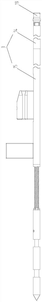
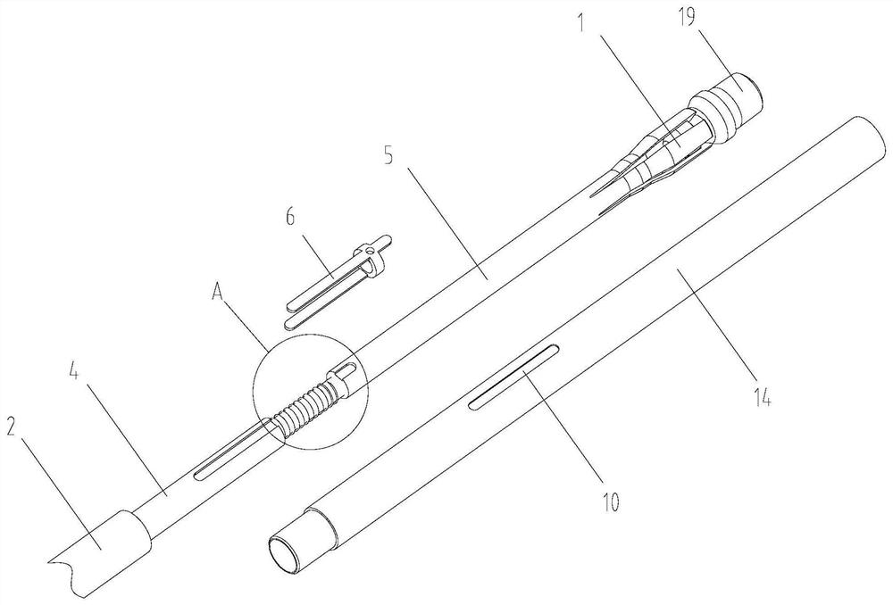
[0040] This embodiment provides a pull rod, such as figure 1 - Figure 5 As shown, it includes: pull claw 1, core rod 2 and adjustment mechanism, pull claw 1 is used to grab fuel rods, pull claw 1 and core rod 2 are connected through an adjustment mechanism, and the adjustment mechanism is suitable for adjusting pull claw 1 and core rod 2 The pull rod also includes a pipe fitting 3, the core rod 2 is set in the pipe fitting 3, one end of the pipe fitting 3 is against the pull claw 1, and the pull claw 1 is suitable for entering or exiting one end of the pipe fitting 3.
[0041] Wherein, the pipe fitting 3 comprises a clamping tube 14 and a sleeve tube 15 clamped with the clamping tube 14, the clamping tube 14 is arranged between the sleeve tube 15 and the pull claw 1, and the adjustment mechanism is located in the clamping tube 14, and the axial dimension of the clamping tube 14 is smaller than the sleeve 15; it should be noted that in this embodiment, the specific structure of...
Embodiment 2
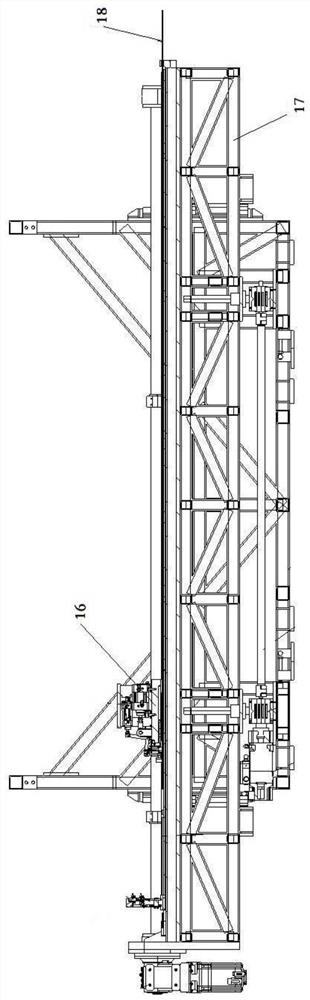
[0060] The rod drawing machine of the present embodiment, as figure 1 As shown, it includes the pull rod described in Embodiment 1, and also includes a slide mechanism 16 and an installation platform 17, and the pull rod 18 is arranged between the slide mechanism and the installation platform 17. Since the pull rod 18 is provided with an adjustment mechanism, the distance between the pull claw 1 and the core rod 2 is shortened or extended by the adjustment mechanism, and then the length of the pull claw 1 extending out of the pipe 3 is adjusted, so that each pull rod can be connected to the end plug of the fuel rod. 19 snap-in, and snap-in at the correct position.
[0061] Compared with the traditional rod pulling machine, which manually moves the fuel rod to connect the fuel rod end plug 19 to the tie rod, the rod pulling machine in this embodiment can greatly save manpower, has low labor intensity, and has higher working efficiency.
PUM
 Abstract
Description
Claims
Application Information
 - R&D Engineer
- R&D Manager
- IP Professional
- Industry Leading Data Capabilities
- Powerful AI technology
- Patent DNA Extraction
Browse by: Latest US Patents, China's latest patents, Technical Efficacy Thesaurus, Application Domain, Technology Topic, Popular Technical Reports.
© 2024 PatSnap. All rights reserved.Legal|Privacy policy|Modern Slavery Act Transparency Statement|Sitemap|About US| Contact US: help@patsnap.com