
Monitoring method of distributed optical fiber sensing system

A distributed optical fiber and sensing system technology, which is applied in the direction of transmitting sensing components, converting sensor output, and measuring devices with optical devices, can solve the problem of prolonging monitoring time, reducing real-time performance of distributed optical fiber sensing systems, and waste of computing resources and other problems, to achieve the effects of improving real-time performance, reducing the workload of solving calculations, and monitoring sensitively

Active Publication Date: 2020-12-04
HUNAN ZHONGDA CONSTR ENG TESTING TECH +1
View PDF5 Cites 2 Cited by
  • Summary
  • Abstract
  • Description
  • Claims
  • Application Information

AI Technical Summary

Problems solved by technology

However, at present, the distributed optical fiber sensing system mostly adopts the uniform acquisition method, that is, the distributed optical fiber sensing system collects the whole data of the monitoring line according to its minimum resolution, and calculates and processes it; It causes a waste of computing resources in the distributed optical fiber sensing system, prolongs the monitoring time, and reduces the real-time performance of the distributed optical fiber sensing system in intelligent monitoring.

Method used


Image

  • Monitoring method of distributed optical fiber sensing system
  • Monitoring method of distributed optical fiber sensing system

Examples


Embodiment Construction

[0031] The specific implementation manners of the present invention will be further described in detail below in conjunction with the accompanying drawings and embodiments. The following examples are used to illustrate the present invention, but are not intended to limit the scope of the present invention.

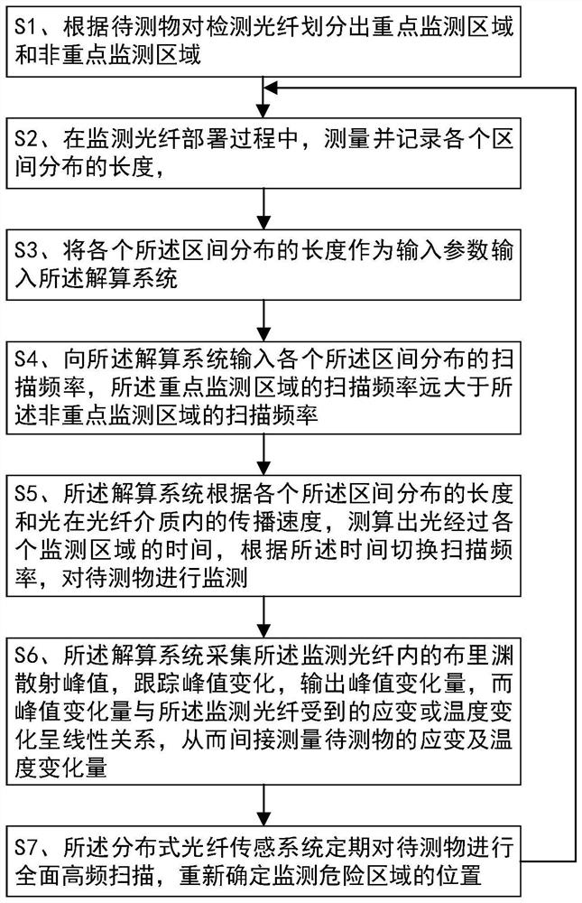
[0032] The distributed optical fiber sensing system of the present invention includes a monitoring optical fiber for data acquisition and transmission, and a solution system for data processing, such as figure 1 shown. For the object to be tested for monitoring optical fibers, there is at least one monitoring dangerous area and its surrounding areas that require key monitoring, and the monitoring resolution and monitoring frequency requirements in key monitoring areas are higher than those in other areas, then the distributed optical fiber sensing system monitoring methods such as figure 2 shown, including the following steps:

[0033] S1. According to the object to be...


PUM


Abstract

The invention discloses a monitoring method of a distributed optical fiber sensing system. The monitoring method comprises the following steps of: S1, dividing a detection optical fiber into a key monitoring area and a non-key monitoring area according to an object to be detected; S2, in the process of monitoring optical fiber deployment, measuring and recording the length of each interval distribution ; S3, inputting the length of each interval distribution into a resolving system as an input parameter; S4, inputting the scanning frequency of each interval distribution into the resolving system, the scanning frequency of the key monitoring area being far greater than the scanning frequency of the non-key monitoring area; S5, enabling the resolving system to calculate the time when the light passes through each monitoring area, and switch the scanning frequency according to the time; and S6, enabling the resolving system to output peak variation so as to measure the strain and temperature variation of the to-be-measured object. According to the method of the invention, the data acquisition range and the data scanning frequency of the distributed optical fiber sensing system are reasonably adjusted, and the data calculation efficiency is improved.

Description

technical field [0001] The invention relates to the technical field of intelligent monitoring, in particular to a monitoring method for a distributed optical fiber sensing system. Background technique [0002] Distributed fiber optic sensors are mainly used to monitor the temperature or deformation of large bridges and tunnels, long-distance transmission pipelines, engineering structures, and industrial production lines. Distributed fiber optic sensors have the advantages of long-distance measurement, but the long monitoring distance and accuracy requirements are inevitable. Increase the calculation amount of data solution in the distributed optical fiber sensing system and reduce the efficiency of measurement and calculation. At the same time, on the distributed optical fiber monitoring line, the monitoring volume at each monitoring point varies in different ranges, and the required monitoring resolutions are also different. For example, for key parts with relatively strict...

Claims


Application Information

Patent Timeline
Patent Type & Authority Applications(China)
IPC IPC(8): G01D5/353
CPCG01D5/35364
Inventor 毕晓猛郭棋武胡泽超
Owner HUNAN ZHONGDA CONSTR ENG TESTING TECH
Learn More