Device and method for monitoring oil stealing and leakage of optical cable in oil pipeline

A monitoring device and oil pipeline technology, applied in measuring devices, pipeline systems, measuring ultrasonic/sonic/infrasonic waves, etc., can solve problems such as difficult to find problems, difficult to timely and accurately find, easy to miss detection period and other problems, and achieve reasonable and good design. effect of effect

Active Publication Date: 2020-12-04
CHINA ELECTRONIS TECH INSTR CO LTD
View PDF8 Cites 2 Cited by
  • Summary
  • Abstract
  • Description
  • Claims
  • Application Information

AI Technical Summary

Problems solved by technology

[0002] In the oil and gas field, the status monitoring of oil pipelines has always been one of the difficulties. As the oil and gas field has higher and higher requirements for intelligence, traditional anti-theft oil technology and leakage monitoring technology are becoming more and more difficult to meet the intelligence of oil and gas pipelines. demand
[0003] Traditional oil pipeline anti-theft oil mostly uses technologies such as manual inspection, video surveillance, drone patrol, negative pressure wave, and optical fiber vibration monitoring. Monitor the area where the camera is deployed, and cannot monitor the complex environment covered by woods, grass and houses; UAV patrol cannot continue to monitor 24 hours, and it is prone to missing inspection periods; negative pressure wave technology can achieve 24 hours Continuous monitoring, but It is not sensitive enough for small flow oil theft and it is difficult to detect it in time; the optical fiber vibration monitoring technology lays out the sensor optical cable outside the oil and gas pipeline, and sends an alarm by sensing the cable vibration during excavation, which can realize 24-hour continuous monitoring, but the optical cable outside the pipe is easy to be deliberately Destruction, after multiple sabotages, the program will not work as expected
At the same time, for oil pipeline leakage monitoring, the traditional technology can only find problems through the change of oil flow rate. This solution is not sensitive to small flow changes, it is difficult to find problems, and it is also impossible to locate the leak point
[0004] Traditional oil pipeline anti-theft oil mostly uses technologies such as manual inspection, video surveillance, drone patrol, negative pressure wave, and optical fiber vibration monitoring. Monitor the area where the camera is deployed, and cannot monitor the complex environment covered by woods, grass and houses; UAV patrol cannot continue to monitor 24 hours, and it is prone to missing inspection periods; negative pressure wave technology can achieve 24 hours Continuous monitoring, but It is not sensitive enough for small flow oil theft and it is difficult to detect it in time; the optical fiber vibration monitoring technology lays out the sensor optical cable outside the oil and gas pipeline, and sends an alarm by sensing the cable vibration during excavation, which can realize 24-hour continuous monitoring, but the optical cable outside the pipe is easy to be deliberately Destruction, after multiple sabotages, the program will not work as expected
At the same time, for oil pipeline leakage monitoring, the traditional technology can only find problems through the change of oil flow rate. This solution is not sensitive to small flow changes, it is difficult to find problems, and it is also impossible to locate the leak point

Method used


Image

  • Device and method for monitoring oil stealing and leakage of optical cable in oil pipeline
  • Device and method for monitoring oil stealing and leakage of optical cable in oil pipeline
  • Device and method for monitoring oil stealing and leakage of optical cable in oil pipeline

Examples


Embodiment Construction

[0339] Below in conjunction with accompanying drawing and specific embodiment the present invention is described in further detail:

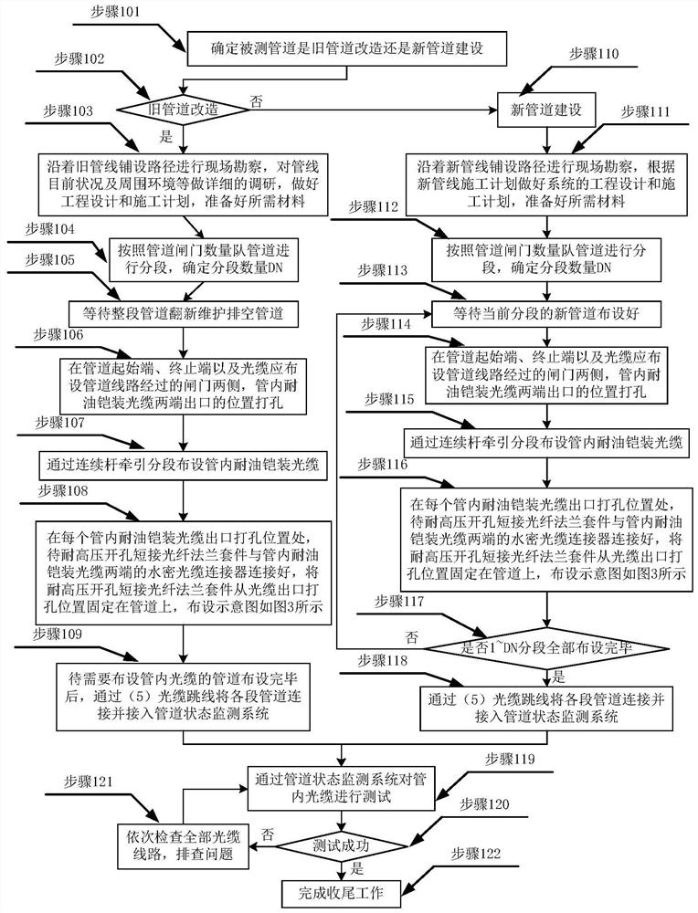
[0340] The present invention is an optical cable oil stealing and leakage monitoring device in an oil pipeline, and the overall scheme is composed as follows figure 1 As shown in , through the main server to control the pipeline status monitoring system at both ends, the optical cables laid in the pipeline are alternately and continuously tested to avoid the failure of the pipeline to cause the optical cable to cause a whole section of the pipeline to be unable to monitor.

[0341] A device for monitoring oil theft and leakage of optical cables in oil pipelines, including a master server 1, a first pipeline status monitoring system 2, a second pipeline status monitoring system 3, a watertight optical cable connector 4, an optical cable jumper 5, and a high-voltage resistant opening Short-circuit fiber optic flange kit 6 and oil-resistant armored...


PUM


Abstract

The invention discloses a device and method for monitoring oil stealing and leakage of an optical cable in an oil pipeline, and belongs to the field of oil and gas storage and transportation and optical fiber sensing. According to the method for monitoring oil stealing and leakage of the optical cable in the oil pipeline, on the basis of the optical fiber vibration distribution testing technical principle, the optical cable is arranged in the oil pipeline, and an event analysis algorithm for vibration distribution data and temperature distribution data of the optical cable in the pipeline is combined, so that damage to the monitored optical cable by lawbreakers is avoided, and when the lawbreakers excavate the pipeline and drill the pipeline, through analyzing the vibration distribution data in the monitored oil pipeline and combining the characteristic difference between the vibration data at the moment and the vibration data in the pipeline at ordinary times, an early warning can begiven for a timely oil stealing event; and when oil and gas of the pipeline leak, through analyzing and early warning vibration changes generated during pipeline leakage and temperature distribution data changes of the oil pipeline, leakage points are found in time and disposed in time, and losses caused by follow-up environmental pollution problems due to oil and gas leakage are avoided and reduced.

Description

technical field [0001] The invention belongs to the fields of oil and gas storage and transportation and optical fiber sensing, and in particular relates to a device and method for monitoring oil theft and leakage of optical cables in oil pipelines. Background technique [0002] In the oil and gas field, the status monitoring of oil pipelines has always been one of the difficulties. As the oil and gas field has higher and higher requirements for intelligence, traditional anti-theft oil technology and leakage monitoring technology are becoming more and more difficult to meet the intelligence of oil and gas pipelines. demand. [0003] Traditional oil pipeline anti-theft oil mostly uses technologies such as manual inspection, video surveillance, drone patrol, negative pressure wave, and optical fiber vibration monitoring. Monitor the area where the camera is deployed, and cannot monitor the complex environment covered by woods, grass and houses; UAV patrol cannot continue to m...

Claims


Application Information

Patent Timeline
IPC IPC(8): F17D5/06G01H9/00
CPCF17D5/06G01H9/004
Inventor 袁明李立功盛立文闫继送乔山葛崇琳张洋李明达郎金鹏王建国方玉朝李述标董杰
Owner CHINA ELECTRONIS TECH INSTR CO LTD
Why Eureka
Try Eureka