Damping bearing seat

A bearing seat and bearing technology, applied in the field of sliding parts, can solve the problems of large bearing force, small internal space, long working time, etc., and achieve the effects of slowing bearing vibration, slowing lateral vibration and improving heat dissipation

Active Publication Date: 2020-12-04
HUNAN MEIBEIDA TECH CO LTD
View PDF9 Cites 0 Cited by
  • Summary
  • Abstract
  • Description
  • Claims
  • Application Information

AI Technical Summary

Problems solved by technology

[0005] Aiming at the deficiencies of the prior art, the present invention provides a shock-absorbing bearing seat, which has the effect of fully buffering the bearing and reducing noise, and has a cavity inside to facilitate the heat dissipation of the bearing, and is convenient to install and facilitate later maintenance, which solves the problem of The traditional buffer surface is too limited, the base buffer is used, which can only buffer the lateral vibration, the force on both sides of the bearing is too large, the pressure on both sides is greater, the installation is troublesome, the fixing effect is poor, it is not convenient for later maintenance, and the noise reduction effect Poor, small internal space, long working hours, lack of cooling effect

Method used


Image

  • Damping bearing seat
  • Damping bearing seat
  • Damping bearing seat

Examples


Embodiment 1

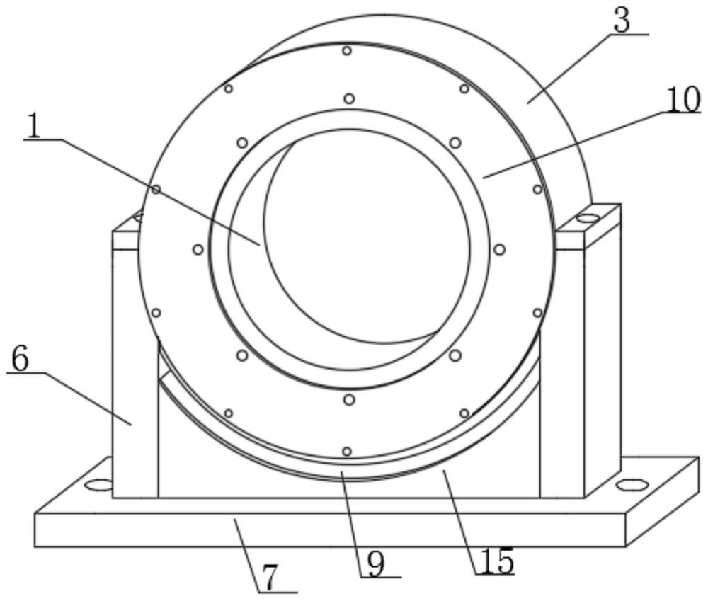
[0029] Such as figure 1 As shown, a shock-absorbing bearing seat includes a bearing body 1, a bearing seat 2 is provided at the bottom of the outer surface of the bearing body 1, and a bearing cover 3 is provided on the top of the bearing seat 2 and located at the top of the outer surface of the bearing body 1. The inner outer surface of the bearing seat 2 and the bearing cover 3 and the outer surface of the bearing body 1 are provided with a positioning ring 4, the outer surface of the positioning ring 4 and the outer surface of the shaft body 1 is provided with a positioning snap ring 5, and the bottom of the bearing seat 2 Support rods 6 are arranged on both sides of the outer surface, bases 7 are arranged between the bottom outer surfaces of the corresponding support rods 6, and slide bars 8 are arranged on both sides of the outer surface of the top of the base 7 and inside the support rods 6, Magnetic strips 9 are provided between the inner sides of the corresponding supp...

Embodiment 2

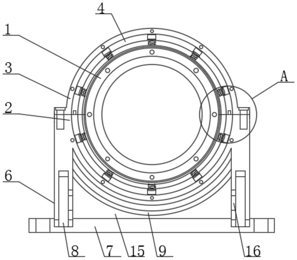
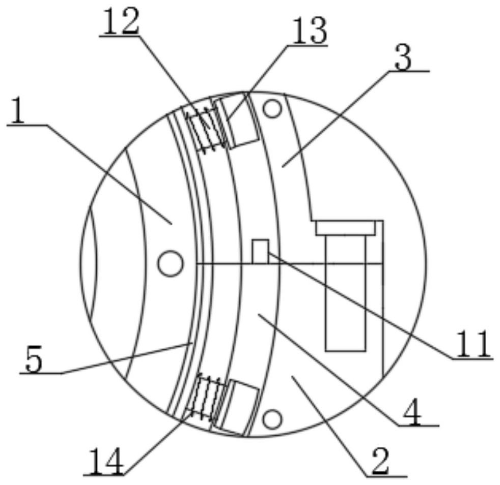
[0033] On the basis of Embodiment 1, such as figure 2 , 3 4. The outer side of the positioning ring 4 shown in 4 is fixedly connected with the inner side of the bearing seat 2 and the inner side of the bearing cover 3. The positioning ring 4 is in the shape of a semicircle, and the outer surfaces of both sides of the positioning ring 4 at the bottom are provided with inserts 11. The insertion strip 11 is fixedly connected with the positioning ring 4 at the bottom, and grooves corresponding to the insertion strip 11 are provided on both outer surfaces of the positioning ring 4 at the top.

[0034] There are multiple groups of inserting rods 12 arranged between the inner outer surface of the positioning ring 4 and the outer outer surface of the positioning clip 5, the inserting rods 12 are fixedly connected to the outer outer surface of the positioning clip 5, and the bottom of the inserting rods 12 is positioned at the positioning The inside of the ring 4 is provided with a l...

Embodiment 3

[0037] On the basis of embodiment one and embodiment two, such as Figure 5 , 6As shown, the outer surface of the bottom of the bearing seat 2 is fixedly connected to the magnet bar 9 on the top, and the corresponding magnet bars 9 are all arc-shaped, and the corresponding magnet bars 9 are of the same polarity, and the bottom outer surface of the magnet bar 9 at the bottom is A magnet base 15 is arranged between the top outer surfaces of the base 7, and the magnet base 15 is fixedly connected with the magnet bar 9 at the bottom and the top outer surface of the base 7.

[0038] The both sides outer surface of magnet seat 15 is tangent to the inner outer surface of support bar 6, and connecting block 16 is arranged between the both sides outer surface of magnet seat 15 and the inner outer surface of slide bar 8, and connecting block 16 and magnet seat 15 and The support rods 6 are all fixedly connected, and the inside of the support rod 6 is provided with a chute corresponding...


PUM


Abstract

The invention relates to the technical field of sliding parts, and discloses a damping bearing seat. The damping bearing seat comprises a bearing body; a bearing seat body is arranged at the bottom ofthe outer surface of the outer side of the bearing body; a bearing cover is arranged at the top of the bearing seat body and located at the top of the outer surface of the outer side of the bearing body; positioning rings are arranged on the outer surfaces of the inner sides of the bearing seat body and the bearing cover and located on the outer side of the bearing body; positioning clamping rings are arranged on the outer sides of the positioning rings and located on the outer surface of the outer side of a rotating shaft body; supporting rods are arranged on the two sides of the outer surface of the bottom of the bearing seat body; a base is arranged between the outer surfaces of the bottoms of the corresponding supporting rods; sliding rods are arranged on the two sides of the outer surface of the top of the base and located in the supporting rods; and magnet strips are arranged between the inner sides of the corresponding supporting rods and located on the top of the base and theouter surface of the bottom of the bearing seat body. The damping bearing seat has the effects of wear resistance and shock absorption, and noise of equipment is reduced through combined use of the corresponding magnet strips.

Description

technical field [0001] The invention relates to the technical field of sliding parts, in particular to a shock-absorbing bearing seat. Background technique [0002] The turntable bearing seat is a large and extra large bearing seat that can withstand comprehensive loads and has a special structure. It has the characteristics of compact structure, sensitive rotation, and convenient installation and maintenance. Where there is a bearing, there must be a support point. The inner support point of the bearing is the shaft, and the outer support is what is often called the bearing seat. [0003] The slewing support bearings in the existing published patents CN108547862A and CN106224388A have disadvantages during use. First, the buffer surface is too limited, and the base buffer can only buffer lateral vibration, and the force on both sides of the bearing If it is too large, the pressure on both sides will be greater. Secondly, the installation is troublesome, the fixing effect is...

Claims


Application Information

Patent Timeline
IPC IPC(8): F16C27/00F16C27/06F16C27/02F16F15/08F16F6/00
CPCF16C27/00F16C27/06F16C27/063F16F15/085F16F15/03F16C2300/14
Inventor 赵青华李治良梁泽显
Owner HUNAN MEIBEIDA TECH CO LTD
Why Eureka
Try Eureka