A kind of roof waterproof construction equipment and construction method
A technology for construction equipment and construction vehicles, which is applied to tools for roof engineering, roofing, construction, etc., can solve problems such as the inability to automatically add paint, and achieve the effects of convenient operation, improved efficiency, and convenient and fast operation.
- Summary
- Abstract
- Description
- Claims
- Application Information
AI Technical Summary
Problems solved by technology
Method used
Image
Examples
specific Embodiment approach 1
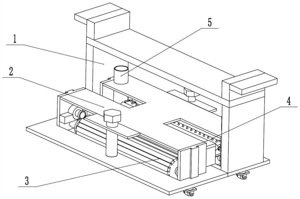
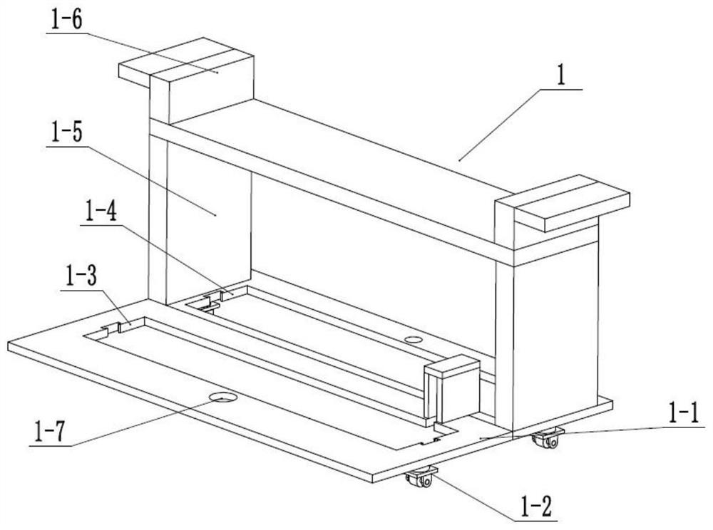
[0028] like Figure 1 to Figure 11As shown, a roof waterproof construction equipment includes a hand-push mobile construction vehicle 1, a construction adjustment frame 2, an impurity cleaner 3, a waterproof coating uniform distributor 4, and two waterproof coating storage adders 5. The construction adjustment Frame 2 is longitudinally slidably connected in hand-push mobile construction vehicle 1, impurity cleaner 3 and waterproof paint spreader 4 are both rotatably connected in construction adjustment frame 2, and two waterproof paint storage adders 5 are fixedly connected in construction adjustment frame 2, two waterproof paint storage adders 5 are attached to and communicated with the two ends of the waterproof paint spreader 4 respectively. Add the waterproof paint to be evenly spread in the two waterproof paint storage adders 5; adjust the distance between the construction adjustment frame 2 and the impurity sweeper 3 and the roof surface by operating the construction adj...
specific Embodiment approach 2
[0034] Such as Figure 1 to Figure 11 As shown, this embodiment will further describe Embodiment 1. The waterproof paint storage adder 5 also includes a side T-shaped slider 5-7, a spring shaft 5-8, a limit block 5-9 and a return spring 5- 10. The side T-shaped slider 5-7 is longitudinally slidably connected in the side T-shaped chute 5-5, the spring shaft 5-8 is fixedly connected to the side T-shaped slider 5-7, and the limit block 5-9 is fixedly connected At the outer end of the spring shaft 5-8, the return spring 5-10 is sleeved on the spring shaft 5-8 and arranged between the side fixing frame 5-6 and the arc switch plate 5-3. The arc-shaped switch plate 5-3 pulled by the displaced switch driving rod 4-5 is displaced for a certain distance, and at the same time, the side T-shaped slider 5-7 is pulled and slides in the side T-shaped chute 5-5, squeezing the return spring 5 -10, the side T-shaped slide block 5-7 makes the communication groove 5-4 communicate with the paint ...
specific Embodiment approach 3
[0035] Such as Figure 1 to Figure 11 As shown, this embodiment further describes the second embodiment, the outer end of the switch driving rod 4-5 is attached to the arc-shaped switch plate 5-3.
PUM
 Abstract
Description
Claims
Application Information
 - R&D Engineer
- R&D Manager
- IP Professional
- Industry Leading Data Capabilities
- Powerful AI technology
- Patent DNA Extraction
Browse by: Latest US Patents, China's latest patents, Technical Efficacy Thesaurus, Application Domain, Technology Topic, Popular Technical Reports.
© 2024 PatSnap. All rights reserved.Legal|Privacy policy|Modern Slavery Act Transparency Statement|Sitemap|About US| Contact US: help@patsnap.com


