An intelligent silt and sand removal pump station for water conservancy projects

A water conservancy engineering, sand-type technology, applied in non-variable-capacity pumps, components of pumping devices for elastic fluids, pumps, etc., can solve problems such as reducing drainage efficiency, affecting water conservancy work efficiency, and easily blocking drainage pipes.

Active Publication Date: 2021-05-07
中交一公局集团水利工程有限公司
View PDF9 Cites 0 Cited by
  • Summary
  • Abstract
  • Description
  • Claims
  • Application Information

AI Technical Summary

Problems solved by technology

[0002] When the pumping station is performing drainage work, the flow of water inside the foundation dam will cause sand, stones, silt, etc. to gather at the water inlet port of the pumping station, and then enter the drainage pipe of the pumping station together with the water, and then output through the pumping equipment , due to the relatively hard sediment, it will cause the sediment to impact the blades of the pumping equipment, resulting in increased wear of the blades of the pumping equipment, and the higher the sediment content, the greater the impact on the head of the pumping equipment, reducing drainage efficiency, and it is easy to block the drain pipe, so if the pump station fails to clean the sand, silt, etc. in the water in time during the drainage process, it will increase the frequency of pump station failures and affect the efficiency of water conservancy work. In view of this, we propose a water conservancy project Using intelligent desilting and sand removal pumping station

Method used


Image

  • An intelligent silt and sand removal pump station for water conservancy projects
  • An intelligent silt and sand removal pump station for water conservancy projects
  • An intelligent silt and sand removal pump station for water conservancy projects

Examples


Embodiment Construction

[0018] The following will clearly and completely describe the technical solutions in the embodiments of the present invention with reference to the accompanying drawings in the embodiments of the present invention. Obviously, the described embodiments are only some of the embodiments of the present invention, not all of them. Based on the embodiments of the present invention, all other embodiments obtained by persons of ordinary skill in the art without creative efforts fall within the protection scope of the present invention.

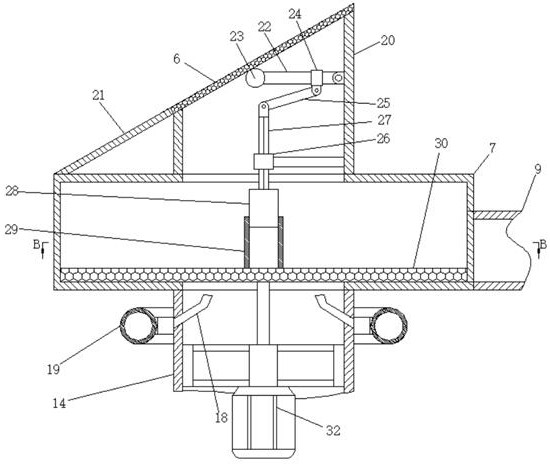
[0019] see Figure 1 to Figure 7 , the present invention provides a technical solution: an intelligent desilting and sand-removing pump station for water conservancy projects, including a pit 1 at the bottom of the foundation dam, the pit 1 is located on the side of the foundation dam for water storage, the A belt conveyor 3 and a centrifugal cylinder 7 for discharging sediment are fixed in the pit 1. The upper and lower ends of the centrifugal cylind...


PUM


Abstract

The invention relates to the field of water conservancy engineering facilities, in particular to an intelligent desilting and sand-removing pumping station for water conservancy engineering, through which the water is sucked into the centrifugal cylinder through the water inlet pipe through the drainage pump fixed on the inner wall of the drainage pipe, and then drained When the sediment concentration detector detects that the sediment concentration in the drainage pipe exceeds the set threshold value, the controller controls the driving part and the drainage pump 2 to work at the same time, so that the water entering the centrifugal column rotates and separates out the sediment in the water. The sediment is automatically discharged, and at the same time, the rapping mechanism is driven to automatically clean the first filter plate. The water flow sensor detects that the water flow in the drain pipe is lower than the set threshold, and the controller controls the recoil mechanism to filter the second filter plate. The plate is flushed to maintain the efficiency of water delivery. This type of water conservancy project uses an intelligent desilting and sand-removing pumping station to realize intelligent desilting and sand-removing water liquid, thereby improving the practical life of the blades of the drainage pump and greatly reducing the failure frequency of the pumping station.

Description

technical field [0001] The invention relates to the field of water conservancy engineering facilities, in particular to an intelligent desilting and sand-removing pumping station for water conservancy engineering. Background technique [0002] When the pumping station is performing drainage work, the flow of water inside the foundation dam will cause sand, stones, silt, etc. to gather at the water inlet port of the pumping station, and then enter the drainage pipe of the pumping station together with the water, and then output through the pumping equipment , due to the relatively hard sediment, it will cause the sediment to impact the blades of the pumping equipment, resulting in increased wear of the blades of the pumping equipment, and the higher the sediment content, the greater the impact on the head of the pumping equipment, reducing drainage efficiency, and it is easy to block the drain pipe, so if the pump station fails to clean the sand, silt, etc. in the water in ti...

Claims


Application Information

Patent Timeline
IPC IPC(8): E03F5/22E03F5/14E03F7/00B04B5/10F04D13/12F04D29/70
CPCB04B5/10E03F5/14E03F5/22E03F7/00F04D13/12F04D29/708
Inventor 张开汤正清高国显刘立强欧阳靖符国平解洋罗谢鑫
Owner 中交一公局集团水利工程有限公司
Why Eureka
Try Eureka