
Electrophoretic coating method

An electrophoretic coating and electrophoresis technology, which is applied in electrophoretic plating, electrolytic coatings, chemical instruments and methods, etc., can solve problems such as affecting the efficiency and effect of electrophoretic coating on workpieces, increasing the rejection rate of electrophoretic coating on workpieces, and ineffective effects. , to achieve the effect of improving market competitiveness, safe and convenient use, and improving efficiency

Inactive Publication Date: 2020-12-04
梁超雄
View PDF9 Cites 2 Cited by
  • Summary
  • Abstract
  • Description
  • Claims
  • Application Information

AI Technical Summary

Problems solved by technology

[0004] The present invention provides a technical solution, which can effectively solve the problem in the above-mentioned background technology that after electrophoresis in the electrophoresis tank, the workpiece will be directly taken out for drying. The drying chamber and the electrophoresis tank are separated and independent, and the workpiece will be moved to the drying chamber after electrophoresis. The required distance is long, and dust fibers are easily attached to the surface, which leads to poor electrophoretic coating effect of the workpiece, which easily leads to an increase in the reject rate of the electrophoretic coating of the workpiece, and affects the efficiency and effect of the electrophoretic coating of the workpiece.

Method used

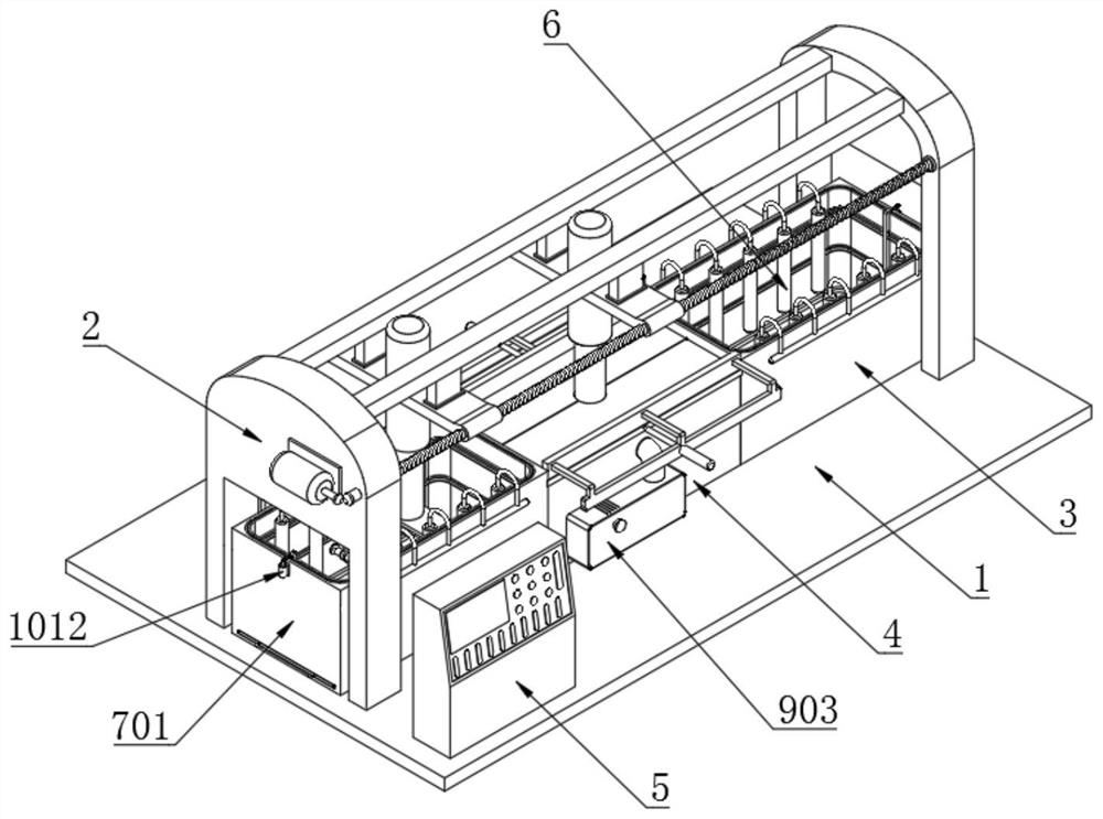
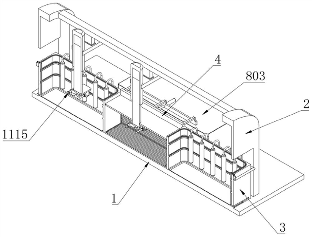

Image

  • Electrophoretic coating method
  • Electrophoretic coating method
  • Electrophoretic coating method

Examples


Embodiment

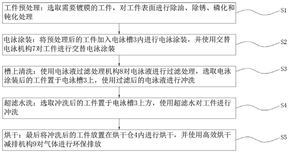
[0044] Example: such as figure 1 As shown, the present invention provides technical scheme, a kind of electrophoretic coating coating method, comprises the steps:

[0045] S1. Workpiece pretreatment: select the workpiece that needs to be coated, and perform degreasing, rust removal, phosphating and passivation treatment on the surface of the workpiece;

[0046] S2. Electrophoretic coating: add the pretreated workpiece into the electrophoretic tank 3 for electrophoretic coating, and use the alternating electrophoretic mechanism 7 to perform alternate electrophoretic coating on the workpiece;

[0047] S3. Cleaning on the tank: use the electrophoretic fluid filtering mechanism 8 to filter the electrophoretic fluid, select the workpiece after electrophoretic coating and place it on the electrophoretic tank 3, and use the filtered electrophoretic fluid to rinse;

[0048] S4. Washing with ultrafiltration water: select the washed workpiece and place it above the electrophoresis tank...


PUM


Abstract

The invention discloses an electrophoretic coating method. The method includes the steps of workpiece pretreatment, electrophoretic coating, on-tank cleaning, ultra-filtration washing and drying. An electrophoretic tank is installed between two side plates; the side plates are installed at the top end of a base plate and used for supporting; and a control table is fixedly installed at the position, corresponding to one side of a drying chamber, of the top end of the base plate. The structure is scientific and reasonable, and usage is safe and convenient; dust fibers attached to the surface ofa workpiece in the moving process can be reduced through a driving motor, the alternate electrophoretic tank, a sliding plate and a mounting connecting plate, the rejection rate of the workpiece is reduced, and the workpiece electrophoretic coating and drying efficiency is improved; and through the arrangement of a water suction pump, an electromagnetic attracting pipe, a separation filter screen,grading filter screens and a storage hopper, iron-containing substances and impurities in the electrophoresis liquid can be collected, the electrophoresis liquid can flow back for use, and the utilization rate of water resources is increased.

Description

technical field [0001] The invention relates to the technical field of electrophoretic coating, in particular to an electrophoretic coating coating method. Background technique [0002] Electrophoretic coating is a coating method that uses an external electric field to make the particles such as pigments and resins suspended in the electrophoretic liquid directional migrate and deposit on the substrate surface of one of the electrodes. The principle of electrophoretic coating was invented in the late 1930s, but it was developed This technology was applied in industry after 1963. Electrophoretic coating is a special coating film formation method developed in the past 30 years. It is the most practical construction process for water-based coatings. It is water-soluble, non-toxic, Easy automatic control and other characteristics, it has been widely used in industries such as automobiles, building materials, hardware, and home appliances; [0003] At present, in the electrophor...

Claims


Application Information

Patent Timeline
Patent Type & Authority Applications(China)
IPC IPC(8): C25D13/22C25D13/20C25D13/24F26B23/06F26B25/00B08B9/087
CPCC25D13/22C25D13/20C25D13/24F26B23/06F26B25/007F26B25/005B08B9/087
Inventor 不公告发明人
Owner 梁超雄
Learn More