Quick heating bathtub equipment for gynaecology and obstetrics
A technology for obstetrics and gynecology and bathtub, applied in the field of rapid heating bathtub equipment for obstetrics and gynecology
- Summary
- Abstract
- Description
- Claims
- Application Information
AI Technical Summary
Problems solved by technology
Method used
Image
Examples
specific Embodiment approach 1
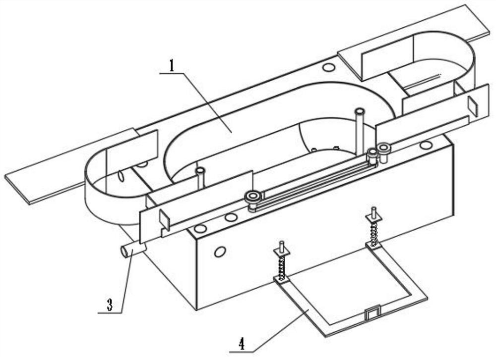
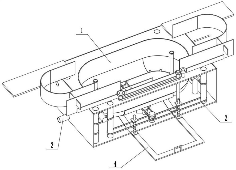
[0032] Combine below figure 1 , figure 2 , image 3 , Figure 4 , Figure 5 , Image 6 , Figure 7 , Figure 8 , Figure 9 , Figure 10 , Figure 11 , Figure 12 , Figure 13 , Figure 14 , Figure 15 , Figure 16 To illustrate this embodiment, the present invention relates to rapid heating bathtub equipment, more specifically, a rapid heating bathtub equipment for obstetrics and gynecology, including a heating mechanism 1, a water circulation mechanism 2, an automatic drainage mechanism 3, and a sliding bed mechanism 4. The equipment can heat the water that will enter the bathtub, the equipment can heat the bathtub, the equipment can keep the water temperature in each position in the bathtub consistent, the equipment can drain water automatically, and the equipment can push the bathtub floor up and form a bed with other parts.
[0033] The heating mechanism 1 is connected with the water circulation mechanism 2 , the water circulation mechanism 2 is connected wi...
specific Embodiment approach 2
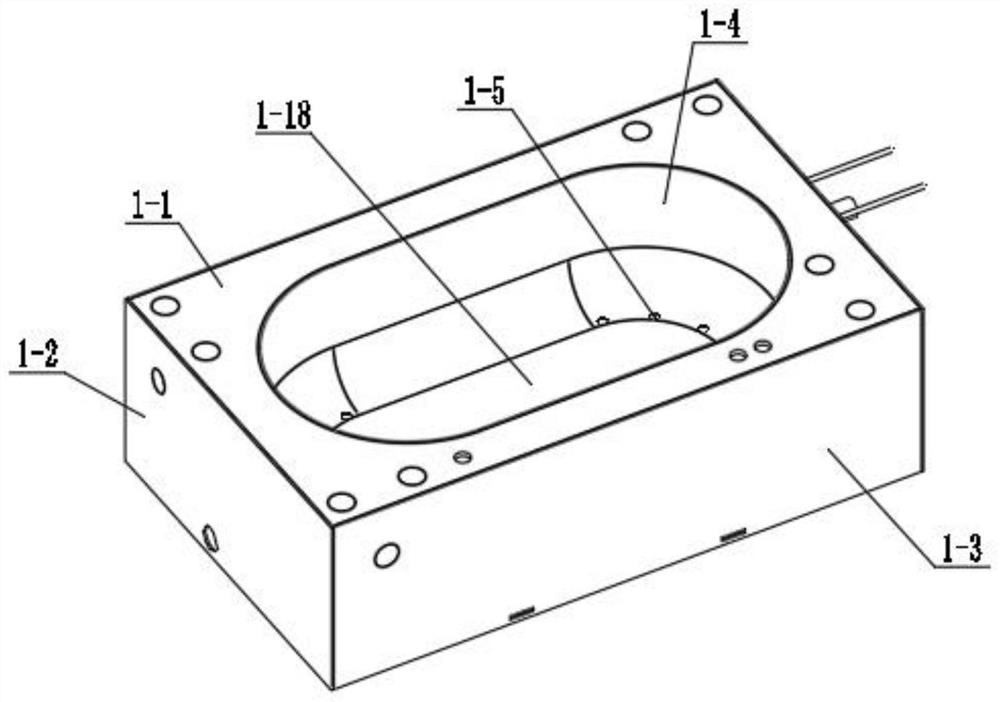
[0035] Combine below figure 1 , figure 2 , image 3 , Figure 4 , Figure 5 , Image 6 , Figure 7 , Figure 8 , Figure 9 , Figure 10 , Figure 11 , Figure 12 , Figure 13 , Figure 14 , Figure 15 , Figure 16 Describe this embodiment, this embodiment will further explain the first embodiment, the heating mechanism 1 includes an upper mounting plate 1-1, a lateral mounting plate 1-2, a vertical mounting plate 1-3, a bathtub forming ring 1- 4. Bathtub inlet hole 1-5, lower mounting plate 1-6, equipment support plate 1-7, electric heater mounting plate 1-8, compression spring a1-9, sliding electric heater 1-10, power contact 1- 11. Power cord 1-12, heating plate 1-13, compression spring b1-14, spring connecting plate 1-15, water inlet pipe 1-16, water inlet 1-17, bathtub sliding bottom plate 1-18, upper mounting plate 1 -1 is connected with the lateral mounting plate 1-2, the lateral mounting plate 1-2 is connected with the vertical mounting plate 1-3, the ve...
specific Embodiment approach 3
[0037] Combine below figure 1 , figure 2 , image 3 , Figure 4 , Figure 5 , Image 6 , Figure 7 , Figure 8 , Figure 9 , Figure 10 , Figure 11 , Figure 12 , Figure 13 , Figure 14 , Figure 15 , Figure 16Describe this embodiment, this embodiment will further explain the first embodiment, the water circulation mechanism 2 includes a power motor 2-1, a motor shaft 2-2, a vertical rotating blade 2-3, a propeller drive belt 2-4, a propeller Shaft 2-5, transmission shaft a2-6, reaction propeller 2-7, belt a2-8, belt b2-9, transmission shaft b2-10, belt c2-11, friction wheel 2-12, belt d2-13, Transmission shaft c2-14, belt e2-15, transmission shaft d2-16, belt f2-17, belt g2-18, transmission shaft e2-19, propeller connecting shaft 2-20, propeller blade 2-21, equipment connection plate 2 -22, power motor 2-1 is connected with motor shaft 2-2, motor shaft 2-2 is connected with vertical rotating blade 2-3, propeller drive belt 2-4 is frictionally connected with...
PUM
 Abstract
Description
Claims
Application Information
 - R&D Engineer
- R&D Manager
- IP Professional
- Industry Leading Data Capabilities
- Powerful AI technology
- Patent DNA Extraction
Browse by: Latest US Patents, China's latest patents, Technical Efficacy Thesaurus, Application Domain, Technology Topic, Popular Technical Reports.
© 2024 PatSnap. All rights reserved.Legal|Privacy policy|Modern Slavery Act Transparency Statement|Sitemap|About US| Contact US: help@patsnap.com


