
Tilia miqueliana drilling equipment for agricultural production

The technology of drilling equipment and linden is applied in the field of linden drilling equipment for agricultural production, which can solve the problems of people's fatigue and increase labor intensity, and achieve the effect of reducing manual operation and improving work efficiency

Pending Publication Date: 2020-12-04
盘丽
View PDF6 Cites 1 Cited by
  • Summary
  • Abstract
  • Description
  • Claims
  • Application Information

AI Technical Summary

Problems solved by technology

[0003] At present, people usually hold the linden with their hands, and then use their feet to control the punching machine to drill the linden. After drilling a hole, people turn the linden to punch another place. , people need to hold the linden tightly, and also need to control the punching machine with their feet, and only one hole can be drilled at a time, which greatly increases people's labor intensity and makes people very tired

Method used


Image

  • Tilia miqueliana drilling equipment for agricultural production
  • Tilia miqueliana drilling equipment for agricultural production
  • Tilia miqueliana drilling equipment for agricultural production

Examples


Embodiment 1

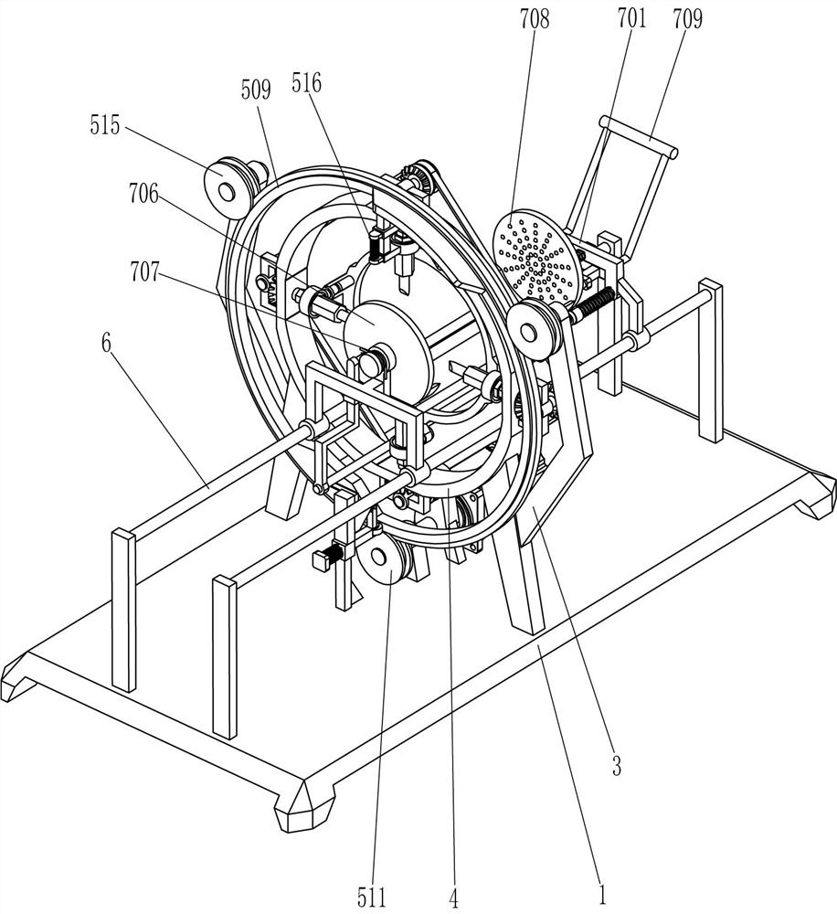
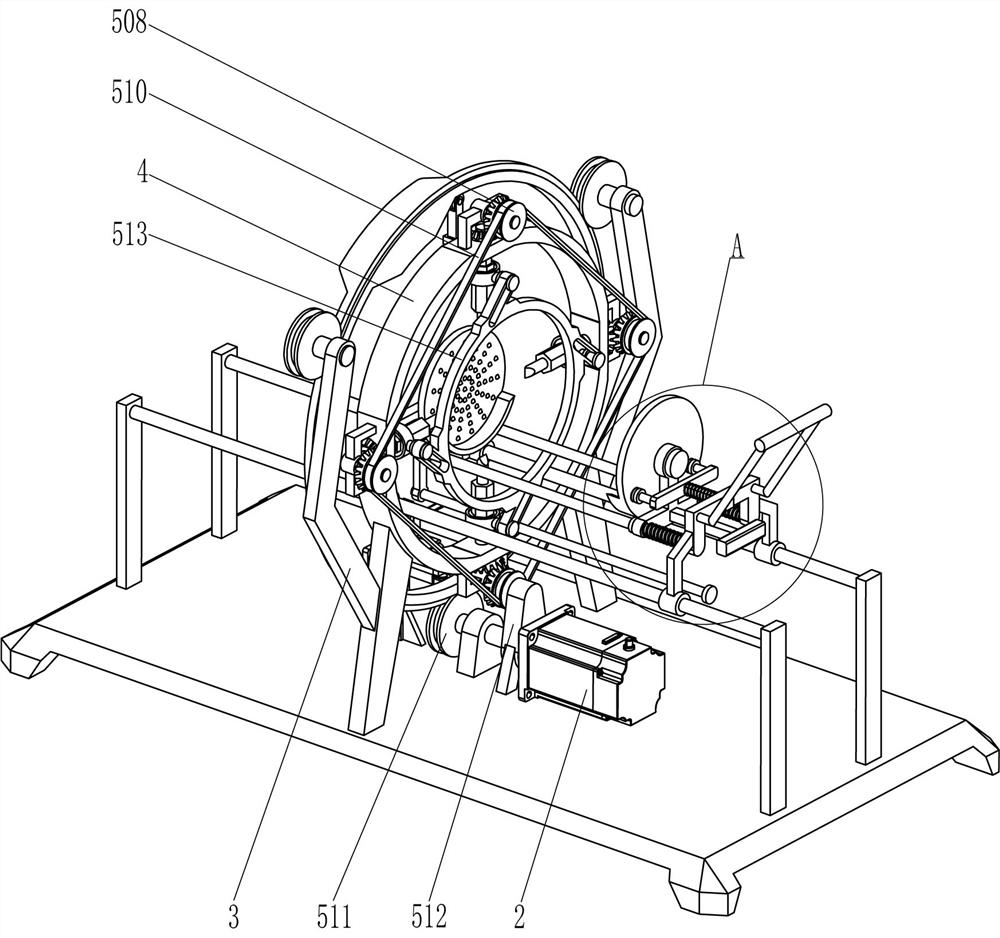
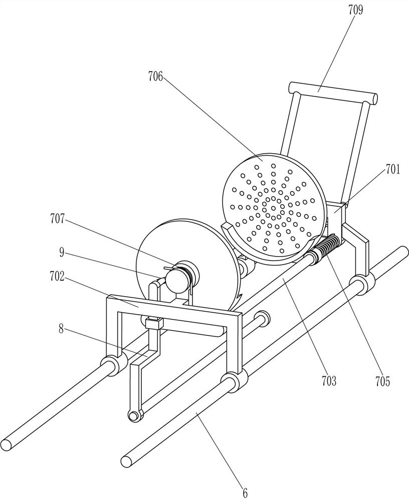
[0024] A kind of wood linden drilling equipment for agricultural production, as attached Figure 1-6 As shown, it includes a bottom plate 1, a servo motor 2, a bracket 3, a mounting frame 4, a drilling assembly 5, a guide rod 6, and a moving assembly 7. The servo motor 2 is installed in the middle of the top of the bottom plate 1 through bolts, and the front and rear sides of the top of the bottom plate 1 are Both brackets 3 and guide rods 6 are installed, two guide rods 6 are located between the two brackets 3, a circular installation frame 4 is connected between the two brackets 3, and the two guide rods 6 pass through the installation frame 4. The drilling assembly 5 is installed on the installation frame 4, and the moving assembly 7 is installed on the guide rod 6.

[0025] When needing to carry out drilling to linden, people fix linden on mobile assembly 7, then start servomotor 2 work, servomotor 2 drives drilling assembly 5 work, and drilling assembly 5 carries out dril...

Embodiment 2

[0031] On the basis of embodiment 1, as attached figure 1 , Figure 4 , Figure 5 and Figure 6 As shown, it also includes a special-shaped rod 8, a first wedge block 10, a support sleeve 11, a contact rod 12, a second wedge block 13 and a second spring 14, and the left side of the second support frame 702 is provided with a special-shaped There is a chute 9 on the left side of the rod 8 and the left side of the placement plate 706, and the chute 9 is slidingly matched with the special-shaped rod 8. The upper part of the left side of the rotating frame 509 is connected with the first wedge block 10, and the middle of the top of the bottom plate 1 is connected with a support sleeve. 11. The support sleeve 11 is located on the left side of the gearbox 512. The contact rod 12 is slidingly provided in the support sleeve 11. The rotating frame 509 is in contact with the contact rod 12. The contact rod 12 is covered with a second spring 14. The second spring 14 The left end is co...


PUM


Abstract

The invention relates to drilling equipment, in particular to tilia miqueliana drilling equipment for agricultural production. The tilia miqueliana drilling equipment for agricultural production enables people to be easier. Tilia miqueliana drilling equipment for agricultural production comprises a bottom plate and brackets, wherein a servo motor is installed on the upper side of the bottom plate;the brackets and guide rods are fixedly connected to the two sides of the top of the bottom plate correspondingly, and the guide rods on the two sides are located between the brackets on the two sides. According to the tilia miqueliana drilling equipment, the tilia miqueliana can be fixed through a moving assembly, the tilia miqueliana can be drilled through a drilling assembly, manual operationis greatly reduced, and people can feel easier; the tilia miqueliana can be pushed to rotate by 45 degrees through a special-shaped rod, so that people do not need to manually rotate the tilia miqueliana, and the working efficiency can be improved; and a sliding frame can be attracted through magnets, so that a placement disc on the right side is not prone to rotating, and people can convenientlyplace the tilia miqueliana in the two placement discs.

Description

technical field [0001] The invention relates to a drilling device, in particular to a basswood drilling device for agricultural production. Background technique [0002] Agricultural production refers to the production activities of planting crops, including the production of crops such as grain, cotton, oil, tea, sugar, vegetables, and fruits. Among them, fungus has high nutritional value and delicate taste, and is one of people's favorite foods , so people will plant some fungus, and when planting fungus, they need to drill holes in the wood linden. [0003] At present, people usually hold the linden with their hands, and then use their feet to control the punching machine to drill the linden. After drilling a hole, people turn the linden to punch another place. , People need to hold the linden tightly, and also need to control the punching machine with their feet, and they can only drill one hole at a time, which greatly increases the labor intensity of people and causes...

Claims


Application Information

Patent Timeline
IPC IPC(8): A01G18/55
CPCA01G18/55
Inventor 盘丽
Owner 盘丽
Learn More