Skin effect measuring device and method

A measuring device and skin effect technology, applied in the direction of current density measurement, measurement using digital measurement technology, etc., can solve the problems of equivalent resistance difference, conductor irregularity, etc., and achieve the effect of realizing measurement and avoiding end effect

Pending Publication Date: 2020-12-01
NANJING UNIV OF INFORMATION SCI & TECH
View PDF11 Cites 0 Cited by
  • Summary
  • Abstract
  • Description
  • Claims
  • Application Information

AI Technical Summary

Problems solved by technology

However, the patent with the publication number CN101465081A pointed out that the problem of using this method to verify the skin effect is that the surface of the conductor is continuous, and the current flowing through the central point connected to the terminal is not the "central current". It is the sum of the "center current" and "surface current" under the path
The observed light and dark changes of the bulb are due to the irregularity of the conductor, resulting in differences in the equivalent resistance of different surface current paths.

Method used


Image

  • Skin effect measuring device and method
  • Skin effect measuring device and method
  • Skin effect measuring device and method

Examples


Embodiment Construction

[0029] The present invention will be further described below in conjunction with accompanying drawings and examples of implementation.

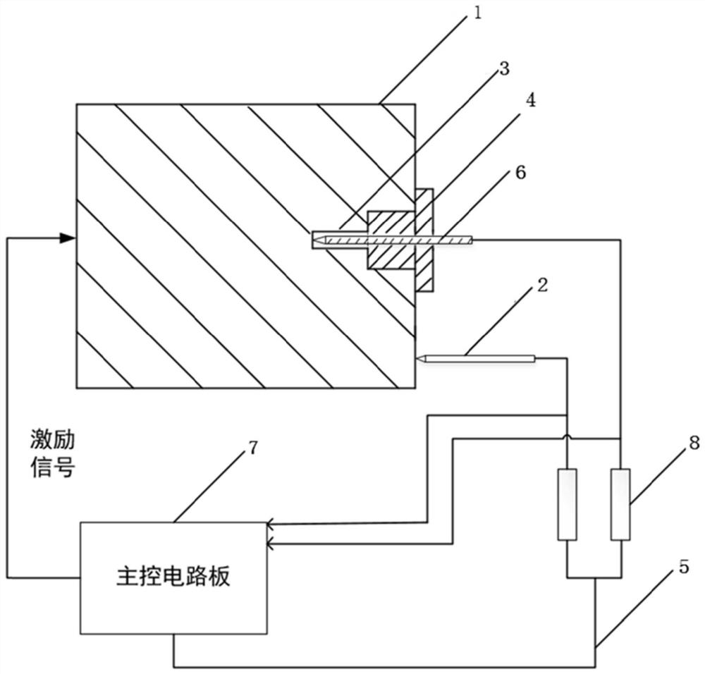
[0030] figure 1 It is a schematic structural diagram of a skin effect measurement device, including a conductor to be tested 1, a second probe 2, a probe hole 3, a probe holder 4, a high-frequency Litz wire 5, an insulator 6, a main control circuit board 7 and a load 8.

[0031] Wherein, the conductor 1 to be tested is a cylindrical copper conductor with a length of 10 cm and a diameter of 5 cm.

[0032] The probe hole 3 includes an upper hole and a lower hole, the upper hole has a depth of 10 mm and a diameter of 10 mm, and the lower hole has a depth of 5 mm and a diameter of 4 mm.

[0033] The probe has a maximum diameter of 3mm and a length of 20mm.

[0034] The probe fixing part 4 is a copper nut, the diagonal diameter of the copper nut is 13 mm, and the length of the bottom is 10 mm.

[0035] The resistance of the connected load is 5...


PUM


Abstract

The invention discloses a skin effect measuring device and method, and the device comprises a to-be-measured conductor which is provided with two end faces which are oppositely arranged in parallel; asignal generation circuit which is used for transmitting an alternating current driving signal which is amplified by a power amplification circuit and then is input into one end surface of the to-be-measured conductor as an excitation signal; a probe hole which is formed in the other end surface of the to-be-detected conductor; a first probe which is inserted into the probe hole; and a second probe, wherein a probe head of the first probe is in contact with the hole bottom of the probe hole, the tail part of the first probe is connected with one end of a first load through a wire, the other end of the first load is connected with a sampling holding circuit, a probe head of the second probe is connected to the same end face of the to-be-detected conductor as the probe hole in an abutting mode, the tail portion of the second probe is connected with one end of a second load through a wire, the other end of the second load is connected with the sampling holding circuit; and signals collected by the sampling hold circuit are transmitted to an upper computer through a serial port communication circuit.

Description

technical field [0001] The invention relates to the field of automatic control, in particular to a skin effect measuring device and a measuring method thereof. Background technique [0002] When direct current is passed into the conductor, it can be considered that the distribution of current is uniform on any cross-section of the conductor, that is, the current on the cross-section is equal everywhere. When alternating current is applied, due to electromagnetic induction, the current will be unevenly distributed in the wire, the current density at the axis is low, and the current density at the surface of the wire is relatively large, showing a skin-like phenomenon. That is, the effective area flowing through the conductor is reduced, and the AC impedance at this time is also greater. When the AC frequency is increased and reaches a certain frequency, this phenomenon is more significant, and this phenomenon is called the skin effect or the skin effect. [0003] Due to the...

Claims


Application Information

Patent Timeline
IPC IPC(8): G01R19/08G01R19/25
CPCG01R19/08G01R19/25
Inventor 吕富勇陆升阳何浩柳加旺康俊鹏巫江涛江鸿周家豪尹伊然
Owner NANJING UNIV OF INFORMATION SCI & TECH
Why Eureka
Try Eureka