Shearing amount calibration device and method for transverse shearing interference wavefront sensor

A wavefront sensor and transverse shearing technology, used in measuring devices, instruments, scientific instruments, etc., can solve the problems of difficulty in accurately determining the relative position and large errors, and achieve the goal of eliminating calibration errors, reducing complexity and accurate calibration results. Effect

Pending Publication Date: 2020-12-01
SHANGHAI INST OF OPTICS & FINE MECHANICS CHINESE ACAD OF SCI
View PDF1 Cites 3 Cited by
  • Summary
  • Abstract
  • Description
  • Claims
  • Application Information

AI Technical Summary

Problems solved by technology

The shear amount is calibrated based on the characteristic graph of the differential wavefront along the shear direction, which solves the problem of large errors caused by the traditional shear rate calculation method based on geometric formulas because the relative positions of each component are difficult to accurately determine.

Method used


Image

  • Shearing amount calibration device and method for transverse shearing interference wavefront sensor
  • Shearing amount calibration device and method for transverse shearing interference wavefront sensor
  • Shearing amount calibration device and method for transverse shearing interference wavefront sensor

Examples


Embodiment Construction

[0031] In order to make the content, implementation process and advantages of the present invention clearer, the present invention will be further described below in conjunction with the examples and accompanying drawings, but the examples do not limit the protection scope of the present invention. The numbers, symbols and other expressions in the following content correspond to the drawings in the specification.

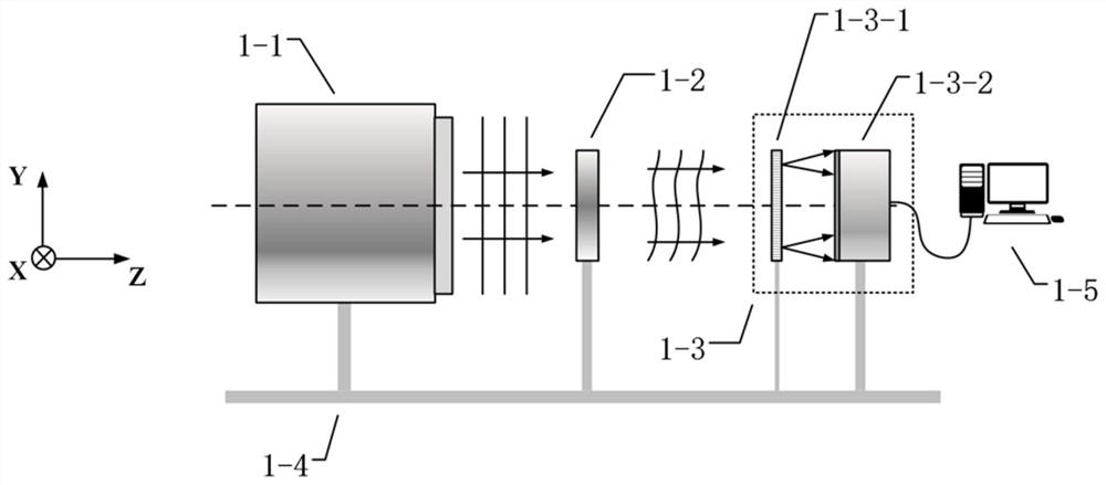
[0032] see figure 1 , as shown in the figure, a shear amount calibration device for a transverse shear interference wavefront sensor, including a wavefront generating device 1-1, a phase step calibration plate 1-2, a wavefront sensor to be calibrated 1-3, and a bracket 1-4, computer 1-5.

[0033] The wavefront generating device 1-1 is used to generate a plane wavefront. The emitted plane wavefront is generated by a point light source after being collimated and beam expanded, and the surface quality of the plane wavefront meets the accuracy requirements of shear c...


PUM


Abstract

The invention relates to a shearing amount calibration device and method for a transverse shearing interference wavefront sensor. The calibration device comprises a collimated light source, a polygonal phase step calibration plate with a known base angle number, and a transverse shearing interference wavefront sensor to be calibrated. According to the calibration method, differential wavefront information in the shearing direction is extracted from an interference pattern acquired by a sensor to be calibrated by using a differential wavefront extraction algorithm, and the shearing amount is calculated in combination with geometrical characteristic distribution of differential wavefront, so that the calibration of the shearing amount of the wavefront sensor is realized.

Description

technical field [0001] The invention belongs to the field of optical transverse shear interference detection, and relates to a shear amount calibration device and method of a transverse shear interference wavefront sensor. Background technique [0002] Transverse shear interferometry is a typical wavefront interferometry technique without a standard mirror. The wavefront to be measured interferes with the superposition of the shear wavefront after its lateral displacement. Compared with traditional interference techniques such as phase-shift point diffraction interference, transverse shearing interference technology can simplify the optical path structure, reduce the difficulty of operation, and has a dynamic range because it does not rely on standard mirrors or pinhole diffraction to generate the required ideal reference wavefront. Large size, easy integration and instrumentation, etc., are often used to test the surface shape of large optical components. In addition, the...

Claims


Application Information

Patent Timeline
Patent Type & Authority Applications(China)
IPC IPC(8): G01J9/02
CPCG01J9/0215
Inventor 彭常哲唐锋王向朝冯鹏李鹏
Owner SHANGHAI INST OF OPTICS & FINE MECHANICS CHINESE ACAD OF SCI
Why Eureka
Try Eureka