Eureka AIR delivers breakthrough ideas for toughest innovation challenges, trusted by R&D personnel around the world.

High-precision part deviation detection system based on 3D visual algorithm

A component deviation and detection system technology, which is applied in the direction of measuring devices, optical testing of flaws/defects, and analysis of solids using sound waves/ultrasonic waves/infrasonic waves, etc. It can solve problems such as high requirements for detection scenarios, time-consuming and labor-intensive manual identification, and large errors.

Active Publication Date: 2020-12-01
广东科优精密机械制造有限公司
View PDF6 Cites 3 Cited by
  • Summary
  • Abstract
  • Description
  • Claims
  • Application Information

AI Technical Summary

Problems solved by technology

[0003] 1. Manual identification is time-consuming and laborious, and is affected by human factors such as fatigue and personal cognitive factors;
[0004] 2. For the detection of high-precision parts, the requirements are relatively high, and the error of traditional detection methods is relatively large;
[0005] 3. For the detection of high-precision parts, the requirements for the detection scene are high, such as the control of the intensity of light irradiation; for small defects, the high light intensity will cause the part to reflect and cover the defect, which is too small and difficult to identify. The traditional detection method has no effect on the above problems. precise control;
[0006] 4. For the detection of high-precision parts, its internal defects are difficult to detect, and the traditional detection equipment does not have the function of identifying the type of parts, and it is impossible to implement different detection methods for different parts

Method used


Image

  • High-precision part deviation detection system based on 3D visual algorithm
  • High-precision part deviation detection system based on 3D visual algorithm
  • High-precision part deviation detection system based on 3D visual algorithm

Examples


Embodiment Construction

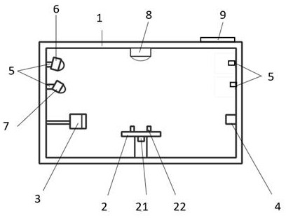
[0070] The above and other technical features and advantages of the present invention will be described in more detail below in conjunction with the accompanying drawings.

[0071] Preferred embodiments of the present invention are described below with reference to the accompanying drawings. Those skilled in the art should understand that these embodiments are only used to explain the technical principles of the present invention, and are not intended to limit the protection scope of the present invention.

[0072] It should be noted that, in the description of the present invention, terms such as "upper", "lower", "left", "right", "inner", "outer" and other indicated directions or positional relationships are based on the terms shown in the accompanying drawings. The direction or positional relationship shown is only for convenience of description, and does not indicate or imply that the device or element must have a specific orientation, be constructed and operated in a spec...


PUM


Abstract

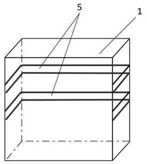
The invention relates to a high-precision part deviation detection system based on a 3D visual algorithm. The high-precision part deviation detection system comprises a detection box body, a supporting circular truncated cone, an ultrasonic detector, a guide rail, a camera, a searchlight and a central controller, wherein the components are precisely controlled by the central controller, control parameters are adjusted, and the difference of detection results caused by the difference of part bodies is reduced; the central controller detects whether a shot image reflects light or not and adjuststhe light brightness, a shooting angle of the searchlight and a position of the searchlight on the guide rail; the central controller establishes model coordinate data according to the 3D algorithm,determines the integrity of acquired data, performs defect detection on qualified part data, and improves the defect detection precision; and an ultrasonic sensor is further arranged to detect the internal defects of the hollow parts in an ultrasonic detection mode, so that the application range of the high-precision part deviation detection system is widened, and the defect detection precision ofdifferent parts is improved.

Description

technical field [0001] The field of the invention is a part deviation detection system, specifically a high-precision part deviation detection system based on a 3D vision algorithm. Background technique [0002] With the development of computer science, there are more and more applications of computers in the industrial field. Artificial intelligence, computer vision algorithms, and neural network algorithms have gradually matured, making their application prospects more and more broad. The 3D camera can collect every The 3D coordinate information of the point is restored intelligently to obtain 3D stereoscopic imaging through 3D vision algorithm, which will not be easily affected by the external environment and complex light, and the technology is more stable, which can solve the problems of poor two-dimensional experience and security in the past, and Widely used in the fields of face recognition and 3D modeling; in the development of industry, traditional part defect dete...

Claims


Application Information

Patent Timeline
IPC IPC(8): G01B11/24G01N21/88G01N29/04
CPCG01B11/24G01N21/8851G01N29/04G01N2021/8874
Inventor 刘振亭籍永强
Owner 广东科优精密机械制造有限公司
Why Eureka
Eureka Blog
Learn More