A chip inductor automatic soldering machine
What is Al technical title?
Al technical title is built by PatSnap Al team. It summarizes the technical point description of the patent document.
An automatic welding and inductance technology, applied in welding equipment, tin feeding devices, manufacturing tools, etc., can solve problems such as easy blockage of tin liquid head, poor fluidity, high temperature injury, etc., to prevent incomplete cleaning and accidental burns , high efficiency, and the effect of improving cleanliness
Active Publication Date: 2021-10-15
蚌埠市科艺博电子有限公司
View PDF7 Cites 0 Cited by
Summary
Abstract
Description
Claims
Application Information
AI Technical Summary
This helps you quickly interpret patents by identifying the three key elements:
Problems solved by technology
Method used
Benefits of technology
Problems solved by technology
[0006] The purpose of the present invention is to provide an automatic soldering machine for chip inductors, which is used to solve the problem of dipping the coil feet of the inductors in tin liquid when preparing inductors. Because the coils are tightly wound, the coils often contact with the tin liquid head in the tin dipping liquid. Contact, when the tin liquid head touches the surface of the coil, it will bring out the particle dust on the coil surface. The fluidity of the tin liquid and the dust will become poor when it is mixed together, and it will easily block the tin liquid head; Manual cleaning, and after the soldering machine is finished welding, the surface of the welding head is still high temperature, and the tin liquid head is adjacent to the welding head, so it is easy to be injured by the high temperature of the welding head when manually cleaning the tin liquid head. Technical issues with certain potential safety hazards
Method used
Image
Click on the blue label to locate the original text in one second.
Reading with bidirectional positioning of images and text.
Examples
Embodiment 1
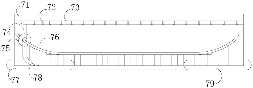
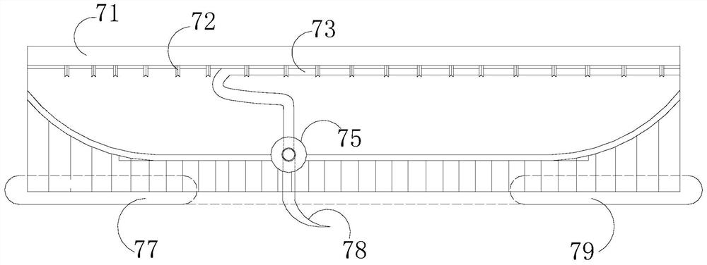
[0029] Such as Figure 1-Figure 6 As shown, the present invention provides a kind of chip inductance automatic soldering machine, and its structure comprises frame 1, motor 2, tin cylinder 3, mounting table 4, solder platform 5, welding head 6, tin liquid head 7, described frame 1 is an L-shaped structure, a solder platform 5 is installed on its horizontal end, a motor 2 is arranged on the vertical end of the frame 1, and the motor 2 drives the welding head 6 and the tin liquid head 7, and the mounting table 4 A tin cylinder 3 is provided, and the tin cylinder 3 is connected with the tin liquid head 7, and the tin liquid head 7 includes a tin inlet tank 71, a pipe jacket 72, a tin liquid pipe 73, a guide pipe 74, a wheel 75, and a slide rail 76. The first wiper 77, the contact head 78, and the second wiper 79. The tin inlet tank 71 communicates with the tin cylinder 3, and the tin liquid pipe 73 is provided at the bottom of the tin inlet tank 71. The connected port, the liqui...
PUM
Abstract
The invention discloses a sheet-shaped inductance automatic soldering machine, the structure of which includes a frame, a motor, a tin cylinder, a mounting platform, a soldering platform, a welding head, and a tin liquid head. The frame is an L-shaped structure, and a The soldering platform is equipped with a motor on the vertical end of the frame, which drives the welding head and the tin liquid head. Tin liquid pipe, guide pipe, running wheel, slide rail, first wiper body, contact head body, second wiper body, the contact head body of the present invention and the running wheel work together, and the running wheel drives the contact head body to move along the slide rail, In order to achieve ductile soldering that satisfies different sizes of transformers, at the same time, during the extension, the contact body needs to pass through the first wiper and the second wiper respectively, and under the joint action of the two wipers, both can Carry out timely mechanical cleaning on the surface of the contact head body to prevent the problems of insufficient cleaning and accidental burns caused by manual cleaning.
Description
technical field [0001] The invention relates to the technical field of inductor processing, in particular to an automatic soldering machine for chip inductors. Background technique [0002] Inductors are one of the three major passive devices in electronic circuits. With the development of surface mount technology, various chip (chip) inductors have emerged. Chip inductors are made of new magnetic materials and precision thin film technology. and automatic winding equipment, so it not only has extremely small size (1.2×2×0.8mm for 1μH, 2.5×3.2×2.5mm for 1000μH), but also has good performance to meet different operating frequencies. and working current requirements. Solder is an important industrial raw material for connecting electronic components in welding lines, and it is often necessary to perform soldering operations on various electronic components. [0003] While the existing automatic soldering machines are in use, the following disadvantages often occur: [0004]...
Claims
Application Information
Patent Timeline
Application Date:The date an application was filed.
Publication Date:The date a patent or application was officially published.
First Publication Date:The earliest publication date of a patent with the same application number.
Issue Date:Publication date of the patent grant document.
PCT Entry Date:The Entry date of PCT National Phase.
Estimated Expiry Date:The statutory expiry date of a patent right according to the Patent Law, and it is the longest term of protection that the patent right can achieve without the termination of the patent right due to other reasons(Term extension factor has been taken into account ).
Invalid Date:Actual expiry date is based on effective date or publication date of legal transaction data of invalid patent.