
Dust collector floor brush and dust collector using the same

A vacuum cleaner and vacuum head technology, applied in vacuum cleaners, suction nozzles, applications, etc., can solve problems such as high power consumption and short battery life of vacuum cleaners, and achieve the effects of reducing the number of times, reducing reciprocating dragging, and reducing air leakage

Pending Publication Date: 2020-12-01
阳珉
View PDF0 Cites 3 Cited by
  • Summary
  • Abstract
  • Description
  • Claims
  • Application Information

AI Technical Summary

Problems solved by technology

[0007] During the cleaning process, both the vacuum cleaner and the roller brush are in working condition, and the power consumption is high, resulting in a short battery life of the vacuum cleaner

Method used


Image

  • Dust collector floor brush and dust collector using the same
  • Dust collector floor brush and dust collector using the same
  • Dust collector floor brush and dust collector using the same

Examples


Embodiment Construction

[0053] In order to understand the above-mentioned purpose, features and advantages of the present invention more clearly, the present invention will be further described in detail below in conjunction with the accompanying drawings and specific embodiments. It should be noted that, in the case of no conflict, the embodiments of the present application and the features in the embodiments can be combined with each other.

[0054] In the following description, many specific details are set forth in order to fully understand the present invention. However, the present invention can also be implemented in other ways different from those described here. Therefore, the protection scope of the present invention is not limited by the specific details disclosed below. EXAMPLE LIMITATIONS.

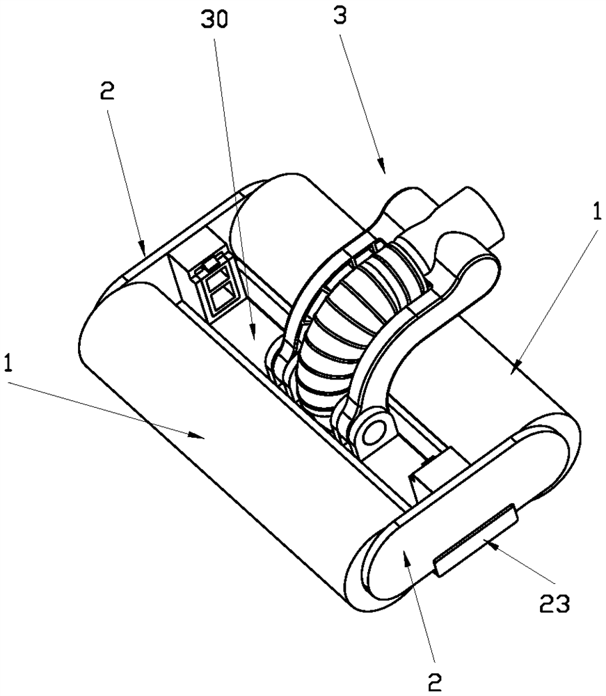
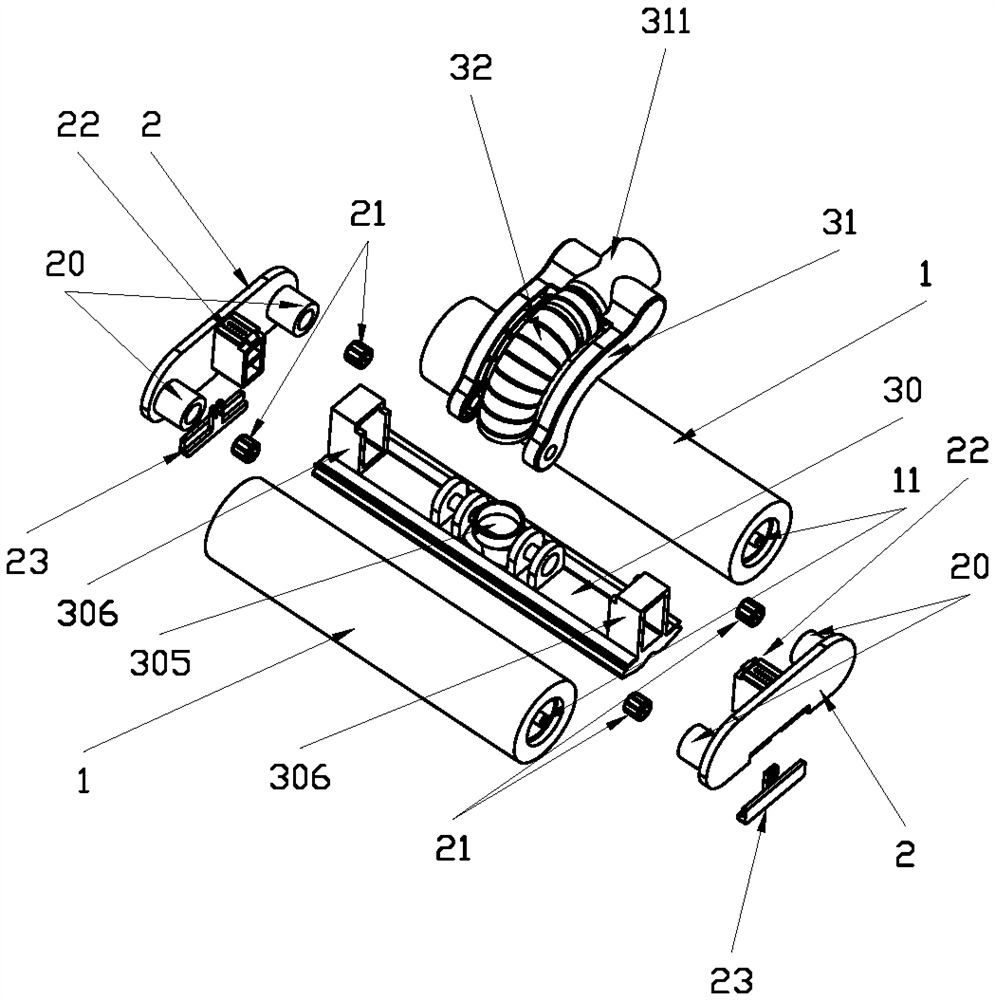
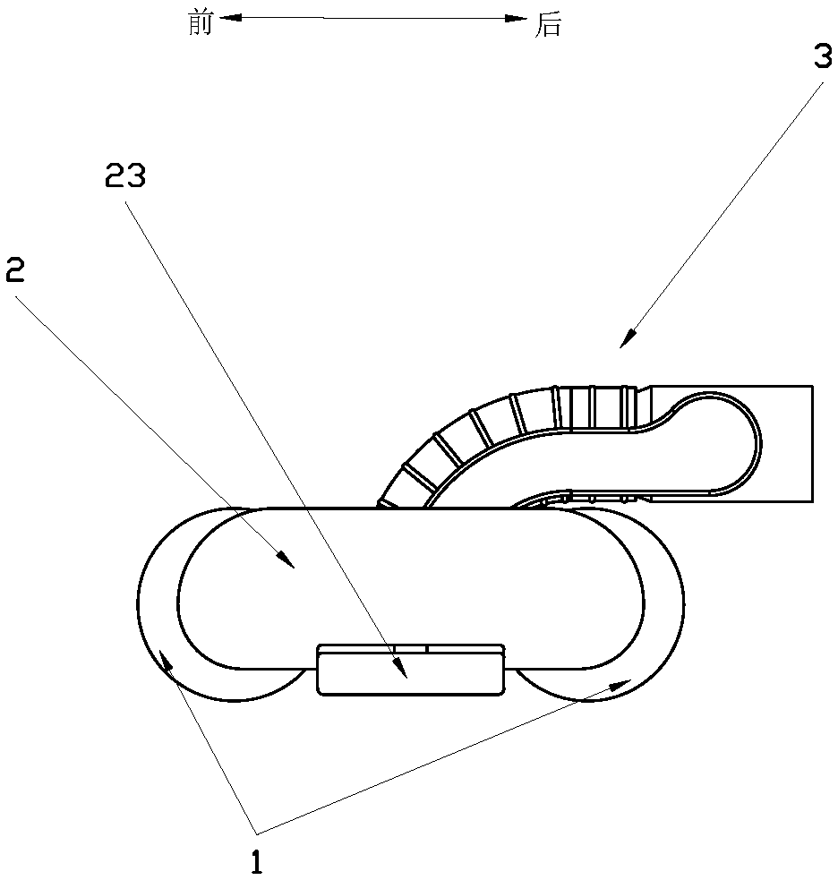
[0055] Refer below Figure 1 to Figure 9 A brush for the vacuum cleaner, a vacuum cleaner, and a wiping roller according to some embodiments of the present invention are described.

[0056] Such as...


PUM


Abstract

The invention discloses a dust collector floor brush and a dust collector using the same. The dust collector floor brush comprises two wiping rollers which are arranged in parallel front and back, thewiping rollers are controlled by a one-way locking mechanism and can only rotate unidirectionally, the locking directions of the two wiping rollers are opposite, when the front wiping roller rolls forwards, the rear wiping roller is locked, and when the rear wiping roller rolls backwards, the front wiping roller is locked, a dust collection head is arranged between the two wiping rollers, the dust collector floor brush and the dust collector can achieve sweeping, mopping and sucking integration, dry and wet dual purposes are achieved, power consumption of the dust collector is reduced, and the beneficial effects of good cleaning effect, high cleaning efficiency and the like are achieved.

Description

technical field [0001] The invention relates to the technical field of dust collection devices, in particular to a dust collector brush and a dust collector. Background technique [0002] The floor brush assembly is one of the main parts of the vacuum cleaner. The motor in the floor brush assembly drives the roller brush to rotate at a high speed to lift up the dust and debris on the ground, and then suck them into the vacuum cleaner through the suction port to clean and remove dust from the ground. Effect. [0003] In the course of realizing the present invention, the inventor finds that there are at least the following problems in the prior art: [0004] The roller brush in the floor brush assembly is mainly used for dust removal. It cannot remove stubborn stains and marks on the floor. After vacuuming, the floor needs to be mopped again, resulting in low cleaning efficiency, time-consuming and laborious. [0005] Since the electric roller brush rolls forward, it is more...

Claims


Application Information

Patent Timeline
IPC IPC(8): A47L9/04A47L9/00
CPCA47L9/00A47L9/04
Inventor 阳珉
Owner 阳珉
Learn More