
Net rack type soil test automatic sample separation device

A technology of geotechnical testing and net frame, which is applied in the direction of measuring devices, sampling, and analyzing materials, etc., can solve the problems of cutting speed, force size and stability, difficulty in controlling, affecting test samples, and low test efficiency, so as to improve geotechnical technology The effect of automation level, ensuring sample quality and improving work efficiency

Pending Publication Date: 2020-11-27
SHANGHAI MUNICIPAL ENG DESIGN INST GRP
View PDF0 Cites 0 Cited by
  • Summary
  • Abstract
  • Description
  • Claims
  • Application Information

AI Technical Summary

Problems solved by technology

[0003] The conventional manual sampling method has the following disadvantages: 1. The test operator needs to hold the sample cutting tool in one hand and hold the soil sample in the other hand, and cut the samples one by one, resulting in low test efficiency; 2. When encountering the original state of hard plastic When cutting soil samples, it requires a lot of effort, and the process is time-consuming and laborious; 3. When manually dividing the original soil samples, multiple cuts are required. It is difficult to control the cutting speed, strength and stability, and the quality of the cut samples is difficult. Guarantee; 4. The size of the artificially divided samples is different, and the flatness of the cutting surface is also difficult to guarantee, which cannot be standardized, which will affect the subsequent production of test samples

Method used


Image

  • Net rack type soil test automatic sample separation device
  • Net rack type soil test automatic sample separation device
  • Net rack type soil test automatic sample separation device

Examples


Embodiment Construction

[0043] The specific embodiments of the present invention will be described in detail below in conjunction with the accompanying drawings, so that those skilled in the art can more clearly understand how to practice the present invention. While the invention has been described in connection with preferred specific embodiments thereof, these embodiments are illustrative only and are not intended to limit the scope of the invention.

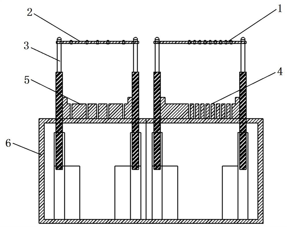
[0044] see Figure 1 to Figure 4 , a grid-type geotechnical test automatic sampling device, including steel wire cutting soil grid, electric push rod 3, combined support, control cabinet 6. The steel wire soil cutting grid frame is arranged on the top of the control cabinet 6 and is horizontally installed on the piston ends of several electric push rods 3 erected, and the fixed end of the electric push rod 3 is installed on the control cabinet 6. The combined support is installed on the top of the control cabinet 6 and corresponds up and down with ...


PUM


Abstract

A net rack type soil test automatic sample separation device comprises a steel wire soil cutting net rack, an electric push rod, a combined support and a control cabinet. The steel wire soil cutting net rack consists of a net rack and a plurality of steel wires; the steel wire soil cutting net rack is arranged over the top of the control cabinet and horizontally installed at the piston ends of themultiple vertically-arranged electric push rods. The fixed end of the electric push rod is installed on the control cabinet, the combined support is installed at the top of the control cabinet and corresponds to the steel wire soil cutting net rack up and down, a gap corresponding to a steel wire of the steel wire soil cutting net rack is formed in the combined support, and a control switch and areset switch for controlling the electric push rod are arranged on the control cabinet. The steel wire soil cutting net rack, the electric push rod and the combined support are adopted for automaticcutting and sample separation, and compared with a traditional manual sample separation mode, the labor is reduced, the working efficiency is improved, the automation level of the geotechnical technology is improved, the separation requirements of samples of different sizes can be met, meanwhile, standardization can be achieved, and the sample quality is guaranteed.

Description

technical field [0001] The invention relates to the field of geotechnical testing indoors for geotechnical engineering survey, in particular to a grid-type automatic sampling device for geotechnical testing. Background technique [0002] When conducting various tests in the geotechnical laboratory, it is necessary to divide the undisturbed soil samples collected from field drilling to make various samples that meet the required size of the test, so as to obtain the physical and mechanical properties of the formation required for engineering design and construction. The undisturbed soil samples drilled from the field are generally Ф108mm in size and 200-300mm in length. According to the engineering requirements, the indoor geotechnical test personnel divide the undisturbed soil samples drilled in the field into samples of different sizes such as 3-10mm in length to further Prepare test specimens of 2 cm in length for routine tests, or 4 cm or 8 cm in length for special tests....

Claims


Application Information

Patent Timeline
IPC IPC(8): G01N1/28
CPCG01N1/286G01N2001/2873
Inventor 田丽霞周黎月余道洋张彬
Owner SHANGHAI MUNICIPAL ENG DESIGN INST GRP
Learn More