Tunnel construction method for short-tube-joint immersed tube

An immersed tube tunnel and construction method technology, applied in artificial islands, water conservancy projects, infrastructure engineering, etc., can solve problems such as high requirements for continuous supply capacity of concrete, long and large volume of immersed tubes, and difficulty in loading barges on immersed tubes , to achieve the effect of reducing configuration requirements and application environment requirements, reducing water depth requirements, and improving prefabrication efficiency

Inactive Publication Date: 2020-11-27
CCCC FOURTH HARBOR ENG CO LTD
View PDF2 Cites 7 Cited by
  • Summary
  • Abstract
  • Description
  • Claims
  • Application Information

AI Technical Summary

Problems solved by technology

[0003] 1. The length of the immersed tube is too long, which makes the weight of the immersed tube very large. Usually, the dry dock method is used for floating towing, which has high requirements for the towing water depth and dry dock site selection; if the semi-submerged barge is used to transport the immersed tube Barge boarding is difficult and risky, and requires a dedicated large-scale semi-submersible barge, which has high requirements for semi-submersible barges, and is difficult to transport in shallow water;
[0004] 2. Due to the large length and volume of the immersed tube itself, it needs to occupy a large space when prefabricating or pouring the immersed tube, and requires a high continuous supply capacity of concrete, and the large-volume immersed tube is easy to crack, resulting in During the operation period, the tunnel leaked, and the later maintenance was very troublesome

Method used


Image

  • Tunnel construction method for short-tube-joint immersed tube
  • Tunnel construction method for short-tube-joint immersed tube
  • Tunnel construction method for short-tube-joint immersed tube

Examples


Embodiment 1

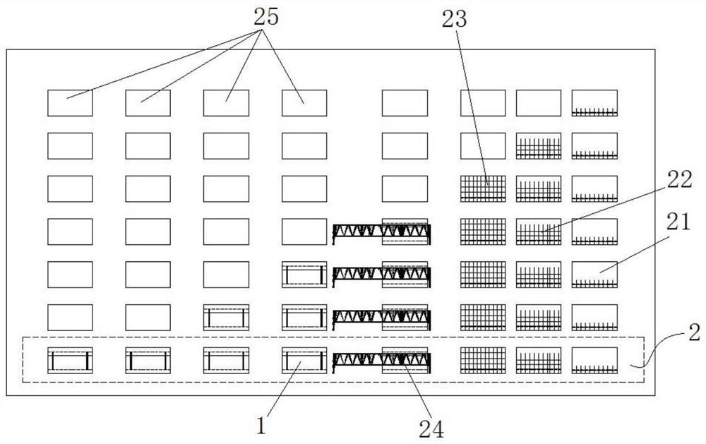
[0044] Such as Figure 1-5 As shown, in this embodiment, a construction method for a short-section immersed-pipe tunnel is provided, which mainly includes the following steps:

[0045] S10. Immersed tube prefabrication:

[0046] The immersed tube 1 is prefabricated in line 2 type, including four parts: steel bar binding, formwork installation, concrete pouring and outfitting; wherein, the concrete pouring is a one-time molding to realize the non-layered and divided parts of the immersed tube 1. section and without construction joints, to reduce the risk of cracking of the immersed tube 1, the length of the immersed tube 1 after forming is 20-30m. In this embodiment, the length of the immersed tube 1 is 22m, so that the immersed tube The size control of the tunnel pipe section meets the self-floating requirements of the single-section immersed pipe 1 at the same time, reducing the difficulty of installation and construction.

[0047] Further, there are several assembly lines ...


PUM

PropertyMeasurementUnit
Lengthaaaaaaaaaa

Abstract

The invention belongs to the technical field of immersed tube engineering, and specifically provides a tunnel construction method for a short-tube-joint immersed tube. The tunnel construction method comprises the following steps: S10, performing assembly line type prefabricating production on the immersed tube, wherein the production comprises concrete pouring which is once forming, and length ofthe formed immersed tube is 20-30m long; S20m transferring the immersed tube onto a semi-submersible barge through a plurality of trolleys, wherein the length direction of the immersed tube is a forward direction thereof, the length direction of the immersed tube is perpendicular to the forward direction of the semi-submersible barge, and depth of immersion of the semi-submersible barge is smallerthan or equal to 3m; and S30, transporting the immersed tube to an immersed tube diving region through the semi-submersible barge, adopting an engineering barrage to pull and position the immersed tube, and adopting a hydraulic crimping method to accomplish underwater butt-joint of adjacent two immersed tubes. The tunnel construction method can effectively simplify barging mounting operation of the immersed tube, reduces construction difficulty, improves operation efficiency, is convenient for quality control of the immersed tube, and ensures tunnel construction quality.

Description

technical field [0001] The invention belongs to the technical field of immersed pipe engineering, and in particular relates to a construction method of a short pipe section immersed pipe tunnel. Background technique [0002] The immersed tubes in the prior art have corresponding specifications and standards for their cross-sectional shapes and sizes, and the commonly used immersed tubes are about 100m in length. Due to their relatively long lengths, during the construction of immersed tube tunnels, the number of tunnels used can be reduced. The number of pipe sections of the immersed tube can effectively reduce the connection nodes between the immersed tubes and reduce the risk of leakage; however, there are the following defects in this structure: [0003] 1. The length of the immersed tube is too long, which makes the weight of the immersed tube very large. Usually, the dry dock method is used for floating towing, which has high requirements for the towing water depth and ...

Claims


Application Information

Patent Timeline
IPC IPC(8): E02D29/073E02D15/08
CPCE02D15/08E02D29/073
Inventor 陈伟彬梁杰忠马亿光明陈猛梁邦炎甘世行史朝杰王晓东李林姜政遥林美鸿
Owner CCCC FOURTH HARBOR ENG CO LTD
Why Eureka
Try Eureka