
Stroke switch assembly machine

A technology of travel switch and assembly machine, applied in electrical switches, metal processing, electrical components, etc., can solve the problems of high cost, long assembly cycle, low efficiency and so on

Inactive Publication Date: 2016-10-05
乐清市华田电力科技有限公司
View PDF9 Cites 67 Cited by
  • Summary
  • Abstract
  • Description
  • Claims
  • Application Information

AI Technical Summary

Problems solved by technology

[0002] The travel switch is also called the limit switch. The travel switch is a commonly used small current master electrical appliance. It uses the collision of the moving parts of the production machinery to make its contacts move to realize the connection or break of the control circuit to achieve a certain control purpose. At this stage, the travel switch The assembly is almost a manual operation. There are human factors in manual assembly, which is prone to defective products, and the assembly cycle is long, low in efficiency and high in cost. In view of this, based on the defects and deficiencies of the existing technology, a travel switch assembly machine is designed.

Method used


Image

  • Stroke switch assembly machine
  • Stroke switch assembly machine
  • Stroke switch assembly machine

Examples


Embodiment Construction

[0040] The preferred embodiments of the present invention will be described in detail below in conjunction with the accompanying drawings, so that the advantages and features of the invention can be more easily understood by those skilled in the art, so as to define the protection scope of the present invention more clearly.

[0041] see Figure 1 to Figure 26 , the embodiment of the present invention includes:

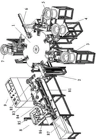
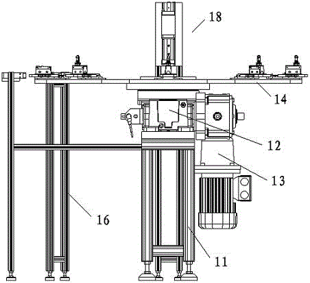
[0042] A travel switch assembly machine, the travel switch assembly machine includes an eight-station turntable mechanism 1, a bottom feeding manipulator 2, a waterproof rubber ring feeding mechanism 3, a snap ring feeding mechanism 4, an apron protective cover feeding mechanism 5, Contact feeding mechanism 6, rivet feeding mechanism 7, labeling assembly line 8 and main electric control cabinet 9, the bottom feeding manipulator 2, waterproof rubber ring feeding mechanism 3, snap ring feeding mechanism 4, rubber ring protection The cover feeding mechanism 5, the conta...


PUM


Abstract

The invention discloses a stroke switch assembly machine, which comprises an eight-working position turntable mechanism, a bottom charging manipulator, a waterproof rubber ring charging mechanism, a clasp charging mechanism, a rubber ring protective cover charging mechanism, a contact charging mechanism, a rivet charging mechanism, a labeling assembly line and a main electric control cabinet, wherein the bottom charging manipulator, the waterproof rubber ring charging mechanism, the clasp charging mechanism, the rubber ring protective cover charging mechanism, the contact charging mechanism and the rivet charging mechanism are annularly located around the eight-working position turntable mechanism; the labeling assembly line is arranged at the left rear side of the eight-working position turntable mechanism; and the rear side of the eight-working position turntable mechanism is provided with the main electric control cabinet. Through the above mode, the manual labor can be replaced, assembly of the stroke switches can be completed automatically, high efficiently and tidily, the labor is saved and the production cost is reduced.

Description

technical field [0001] The invention relates to the field of mechanical automation, in particular to a travel switch assembly machine. Background technique [0002] The travel switch is also called the limit switch. The travel switch is a commonly used small current master electrical appliance. It uses the collision of the moving parts of the production machinery to make its contacts move to realize the connection or break of the control circuit to achieve a certain control purpose. At this stage, the travel switch The assembly is almost a manual operation. There are human factors in manual assembly, which is prone to defective products, and the assembly cycle is long, low in efficiency and high in cost. In view of this, based on the defects and deficiencies of the existing technology, a travel switch assembly machine is designed. . Contents of the invention [0003] The main technical problem to be solved by the present invention is to provide a travel switch assembly ma...

Claims


Application Information

Patent Timeline
Patent Type & Authority Applications(China)
IPC IPC(8): H01H11/00B23P19/00
CPCB23P19/00H01H11/00
Inventor 鲍杨建
Owner 乐清市华田电力科技有限公司
Learn More