
Touch electric fireplace

a technology of electric fireplace and touch, which is applied in the direction of pulse technique, domestic stove or range, furnace, etc., can solve the problems of electric fireplaces potentially displacing traditional fireplaces, unsatisfactory appearance, and the inability to compactly combine switch and button with plane glass or arc glass, so as to simplify traditional buttons and facilitate installation. , the effect of durable and convenien

Active Publication Date: 2013-09-17
LU MIN HSUN
View PDF4 Cites 0 Cited by
  • Summary
  • Abstract
  • Description
  • Claims
  • Application Information

AI Technical Summary

Benefits of technology

The present invention is a touch electric fireplace that allows users to directly touch the surface for operation. The transparent isolator at the front of the fireplace can be formed into a plane or an arc-shaped surface that is convex, making it more stylish and eye-catching. The touch panel, touch unit, and main control board on the fireplace make it easy for users to operate. The transparent isolator completely shields the window and rim, and the touch function allows for easy assembly without needing an opening. The touch area on the transparent isolator is separated from the circuits area, making it waterproof and safe for users. This invention provides a more convenient, durable, and safe product for users.

Problems solved by technology

When the technology progresses everyday, the electric fireplaces are potentially displacing the traditional fireplaces.
Such mechanical switch and flimsy button provide a short using life, and they are typically built with unsatisfactory appearances.
To make matters worse, the switch and the button are unable to be compactly assembled with plane glass or arc glass.
Accordingly, the existing electric fireplaces basically do not cooperate with glass or isolator, so means of a touch control is also unavailable.
Obviously, afore installation is difficult; therefore, the design of electric fireplace is limited, and the research and development are also restricted, which further affects the electric fireplace industry.
Gradually, the existing electric fireplaces can not satisfy users who tend to get quality products.
Further, since the existing electric fireplace defines its flimsy button or mechanical switch at the opening of the front housing, the transparent isolator can not be formed into a compact plane or a convex.
Subsequently, the front cover on the transparent window of the electric fireplace will be designed monotonous, which is accordingly unattractive and unsightly.

Method used


Image

  • Touch electric fireplace
  • Touch electric fireplace
  • Touch electric fireplace

Examples


Embodiment Construction

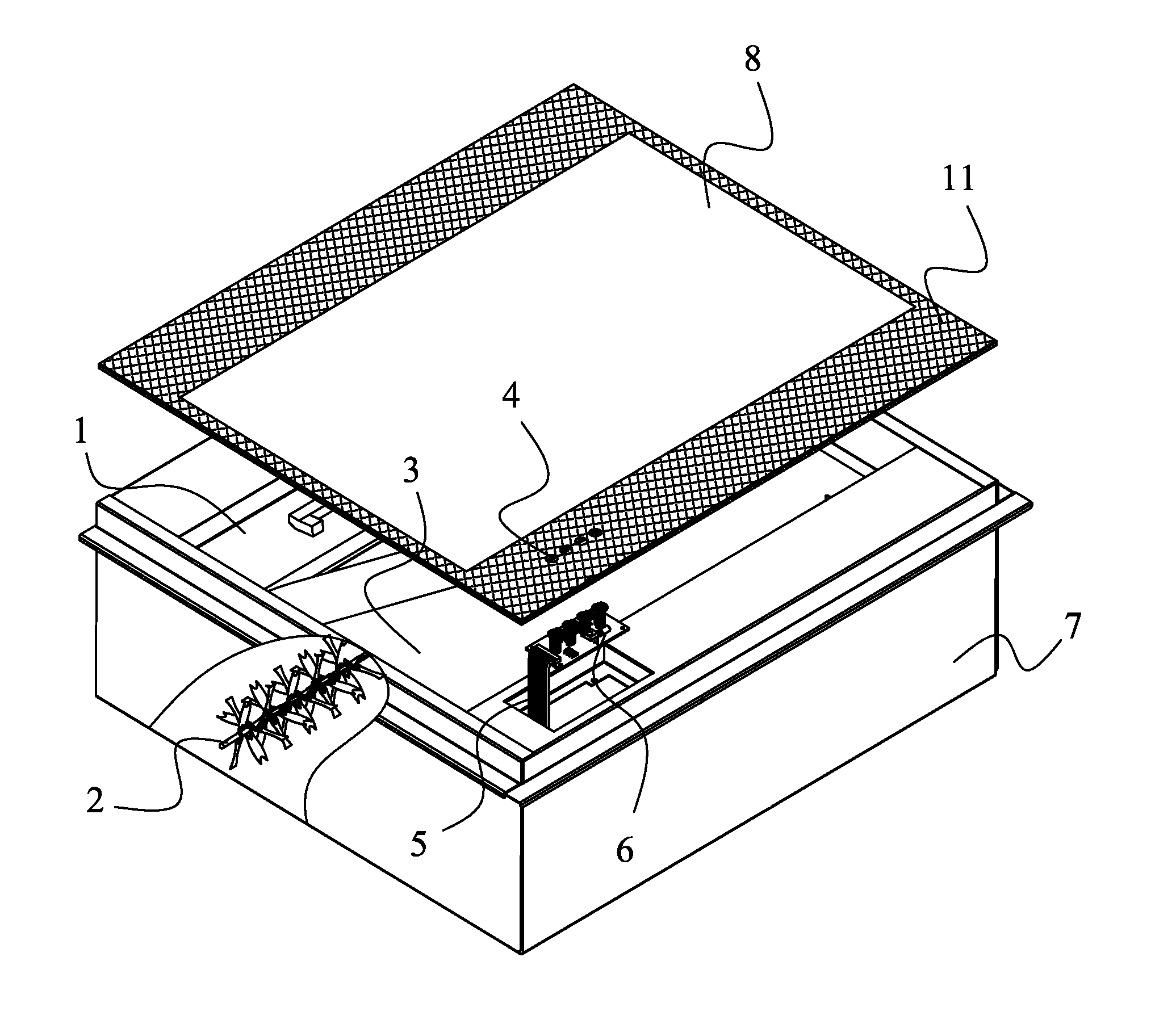
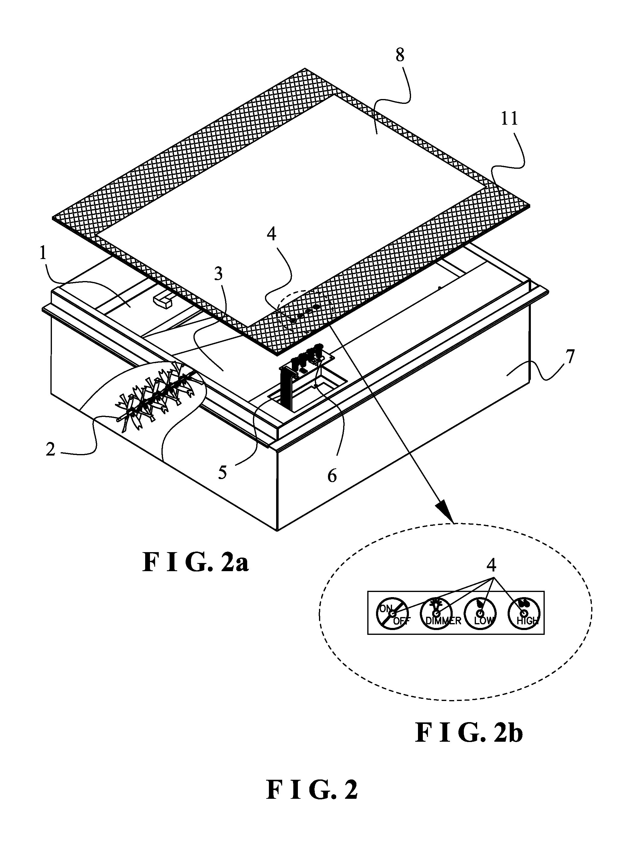
[0021]FIGS. 1 to 4 show a preferred embodiment of the present invention. The touch electric fire place comprises a housing 7, an imaging screen 3, a coal light source 12, an imaging light source, a flame processing device 13, a reflection processing device 2, a transparent isolator 8, a touch unit 6, and a main control board 5.

[0022]Referring to FIG. 1, the housing 7 could be freely built into a classic formation or a stylish formation in accordance with the practical demands. In this embodiment, the housing is generally formed into a rectangular solid, and various components are installed in the housing 7. Especially, a window is defined on a front wall of the housing. Wherein, the transparent isolator 8 could be designed by a plane or a convex that is able to compactly shield a rim of the housing 7. In order to enhance the electric fireplace, a periphery of the transparent isolator 8 is printed by a pattern layer with divergent colors and decorative designs. The transparent isolat...


PUM


Abstract

A touch electric fireplace comprises a housing, an imaging screen installed in the housing, a light source, a flame processing device, and a reflecting module. A window is defined on a front wall of the housing, a transparent insulator completely shields the window as well as a rim of the window, a touch area is arranged on the transparent insulator and along the rim of the window, and a touch panel is attached to a front side of the transparent insulator of the touch area; whereby, the electric fireplace is easily operated and controlled by simply touching the touch panel.

Description

BACKGROUND OF THE INVENTION[0001]1. Field of the Invention[0002]The present invention relates to an electric fireplace, especially to a touch electric fireplace.[0003]2. Description of the Related Art[0004]When the technology progresses everyday, the electric fireplaces are potentially displacing the traditional fireplaces. However, means for operating the electric fireplaces mostly adopts a mechanical switch or a flimsy button. Such mechanical switch and flimsy button provide a short using life, and they are typically built with unsatisfactory appearances. To make matters worse, the switch and the button are unable to be compactly assembled with plane glass or arc glass. Accordingly, the existing electric fireplaces basically do not cooperate with glass or isolator, so means of a touch control is also unavailable. In fact, the flimsy buttons and the mechanical switches have to be installed after an opening is defined on a front housing of the electric fireplace. Obviously, afore in...

Claims


Application Information

Patent Timeline
Patent Type & Authority Patents(United States)
IPC IPC(8): F21V33/00H05B37/02
CPCF24C7/004H03K17/9622H03K2217/96076
Inventor LU, WEI LIN
Owner LU MIN HSUN
Learn More