Textile machine dust collecting device

A dust collection and textile machine technology, applied in textiles, looms, spinning machines, etc., can solve the problems of not effectively removing textile dust, inconvenient for operators, unable to adjust the height, etc., to achieve a perfect filter structure, suitable for popularization and utilization , the effect of simple and convenient disassembly

Inactive Publication Date: 2020-11-27
敖玲玲
View PDF0 Cites 5 Cited by
  • Summary
  • Abstract
  • Description
  • Claims
  • Application Information

AI Technical Summary

Problems solved by technology

[0003] During the production process, the lint on the yarn will be scattered in the air during the pulling and weaving process. A large amount of lint floating in the air is the textile dust generated by the textile machine during the working process, which will cause harm to the workers in the workshop. The relatively large respiratory hazard has seriously affected the life and health of textile workers, and the common textile machines on the market cannot adjust the height of the suction structure, so that the leakage of textile dust to the outside has brought great harm to the use of operators. Inconvenience, and the traditional collection device can not effectively filter the textile dust. When the dust collection is too much or the dust removal effect is reduced due to clogging, it is necessary for professionals to remove the filter device and clean it, and then install it and continue to use it. , affecting the normal use of the dust collector and reducing the production efficiency, it is urgent to design a textile machine dust collection device to solve the above problems

Method used

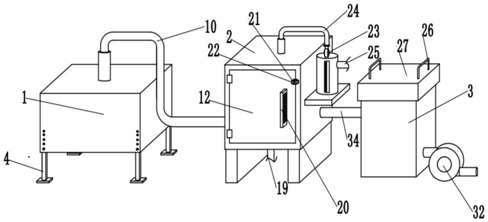
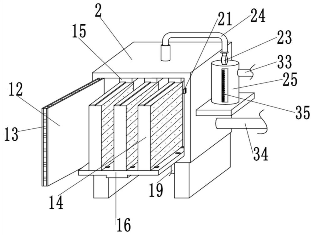
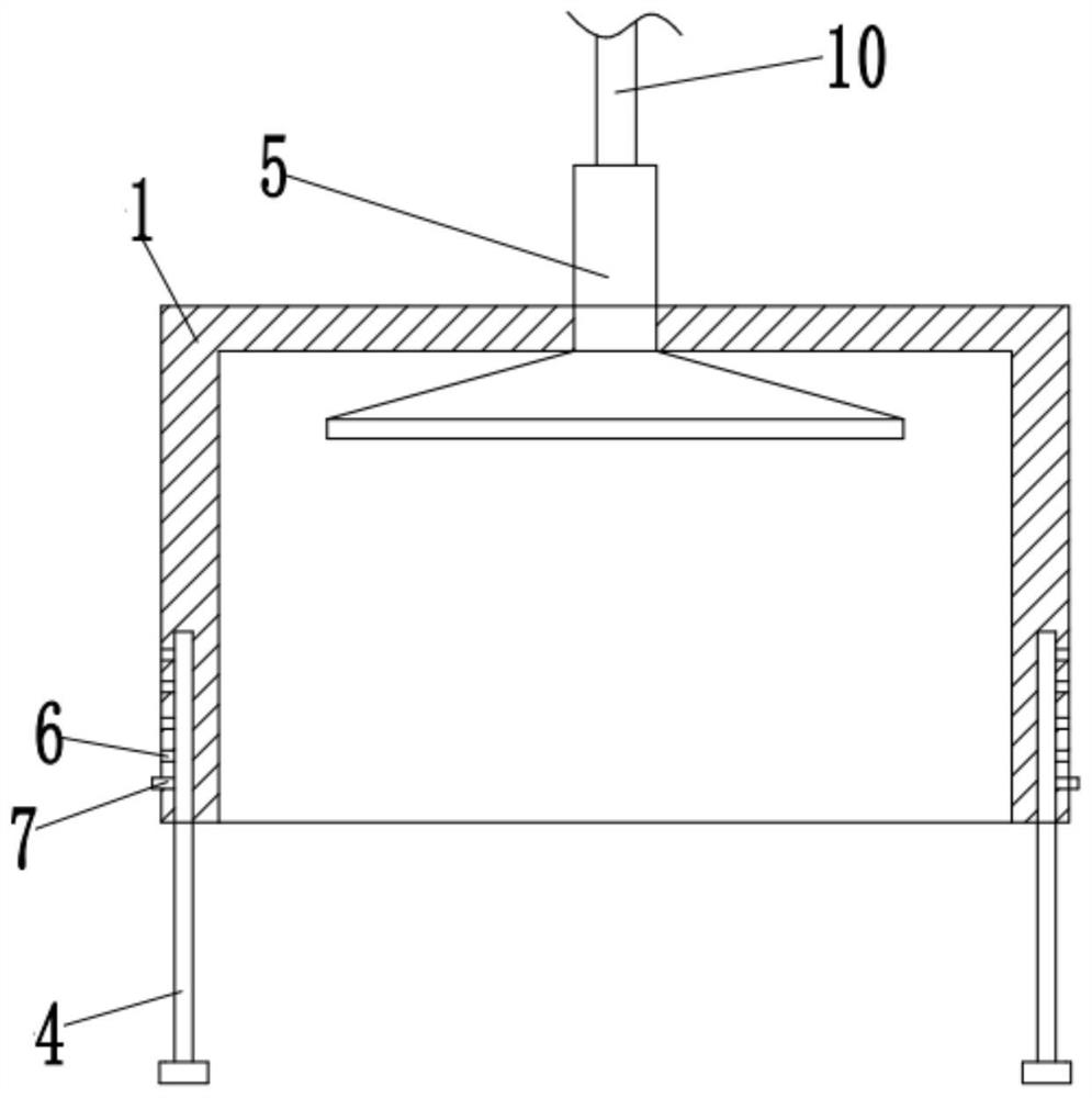

Image

  • Textile machine dust collecting device
  • Textile machine dust collecting device
  • Textile machine dust collecting device

Examples


Embodiment Construction

[0024] The following will clearly and completely describe the technical solutions in the embodiments of the present invention with reference to the accompanying drawings in the embodiments of the present invention. Obviously, the described embodiments are only some, not all, embodiments of the present invention. Based on the embodiments of the present invention, all other embodiments obtained by persons of ordinary skill in the art without making creative efforts belong to the protection scope of the present invention.

[0025] It should be noted that when a component is said to be "fixed" to another component, it can be directly on the other component or there can also be an intervening component. When a component is said to be "connected" to another component, it may be directly connected to the other component or there may be intervening components at the same time. When a component is said to be "set on" another component, it may be set directly on the other component or t...


PUM


Abstract

The invention discloses a textile machine dust collecting device. The textile machine dust collecting device comprises a cover body, a first filtering box and a second filtering box; a sliding grooveis formed in the inner wall of the bottom of the first filtering box, a filtering bottom plate is slidably connected into the sliding groove, a water outlet hole communicating with the filtering bottom plate is formed in the inner wall of the bottom of the first filtering box, a water pipe connected with the water outlet hole is installed on the outer wall of the bottom of the first filtering boxthrough bolts, and three filter plates distributed in a left-right structure at equal intervals are installed on the outer wall of the top of the filtering bottom plate through the bolts. According tothe textile machine dust collecting device, through the arrangement of the filter plates, when a water pump is started, the water pump sprays liquid inside a water tank onto the filter plates througha spray head, so that the filter plates have dust adsorption function, then the dust filtering function of the filter plates is achieved, and the filter plates are simpler and more convenient to disassemble through matched use of the sliding groove and the filtering bottom plate; and a dust filter screen and a dehumidification screen are arranged inside the second filtering box, so that the filter structure of the device is more perfect.

Description

technical field [0001] The invention relates to the technical field of textile machines, in particular to a dust collection device for textile machines. Background technique [0002] Textile machine, also known as textile machine, loom, cotton spinning machine, etc., the ancient textile machine is a loom driven by manpower. The textile machine is the full name of the tool that processes raw materials such as thread, silk, and hemp into silk and then weaves them into cloth. Like spinning pendants, spinning wheels, spindles, pedal looms, as well as modern mechanical looms and modern numerical control automatic looms, the development of ancient and modern textile processes and equipment are all designed in response to textile raw materials. It plays an important role in technology. The fibers used in textiles in various countries in the ancient world are natural fibers, generally three short fibers (wool, hemp, and cotton). [0003] During the production process, the lint on t...

Claims


Application Information

Patent Timeline
Patent Type & Authority Applications(China)
IPC IPC(8): D01H11/00D03J1/00D04B35/32D01H1/16D03D49/02B01D46/00B01D46/10B01D46/12B01D53/26
CPCD01H11/00D03J1/002D01H1/16D03D49/02D04B35/32B01D46/0035B01D46/10B01D46/12B01D53/263B01D46/88
Inventor 敖玲玲
Owner 敖玲玲
Why Eureka
Try Eureka