Preparation method for improving magnetoresistance of anisotropic magnetoresistor
A technology of anisotropic magnetism and magnetoresistance, which is applied in the direction of ion implantation plating, metal material coating process, coating, etc., can solve the problems of reducing production capacity and increasing production cycle, so as to increase production time and improve magnetoresistance The effect of reducing the rate and production cycle
- Summary
- Abstract
- Description
- Claims
- Application Information
AI Technical Summary
Problems solved by technology
Method used
Image

Examples
preparation example Construction
[0037] The preparation method provided by the present invention to improve the magnetoresistance rate of anisotropic magnetoresistance specifically comprises the following steps:
[0038] Step 1, cleaning the silicon wafer, and fixing the clean silicon wafer to the sample tray in the sputtering chamber;
[0039] Step 2. Pump the sputtering chamber to a high vacuum. When the vacuum degree is lower than the set value, argon gas is introduced; the set value can be 5×10 -4 Pa;
[0040] Step 3: Turn on the high-energy ion source, the high-energy ion source cleans the silicon wafer, and turn off the high-energy ion source after the cleaning is completed;
[0041] Step 4. Set the sputtering power from 60W to 2000W, set the sputtering bias voltage from 0V to 300V, set the sputtering time from 2min to 30min, and keep the working pressure of the sputtering chamber between 0.2Pa and 2Pa;
[0042] Step 5: Start sputtering NiFe according to the parameters set in Step 4, and at the same t...
Embodiment 1
[0057] The specific preparation process of NiFe is as follows,
[0058] Step 1. Use isopropanol to clean the silicon wafer with an ultrasonic cleaner, and fix the clean silicon wafer to the sample tray in the sputtering chamber;
[0059]Step 2. Use a molecular pump to draw a high vacuum, when the vacuum degree is better than 8×10 -5 At the time of Pa, argon gas with a purity of 99.999% is introduced;
[0060] Step 3: Turn on the high-energy ion source, the high-energy ion source cleans the silicon wafer, and turn off the high-energy ion source after the cleaning is completed;
[0061] Step 4. Set the sputtering power to 200W, the bias voltage to 100V, set the sputtering time to 600s, keep the speed of the sample disc at 5r / min, and keep the working pressure at about 0.3Pa;
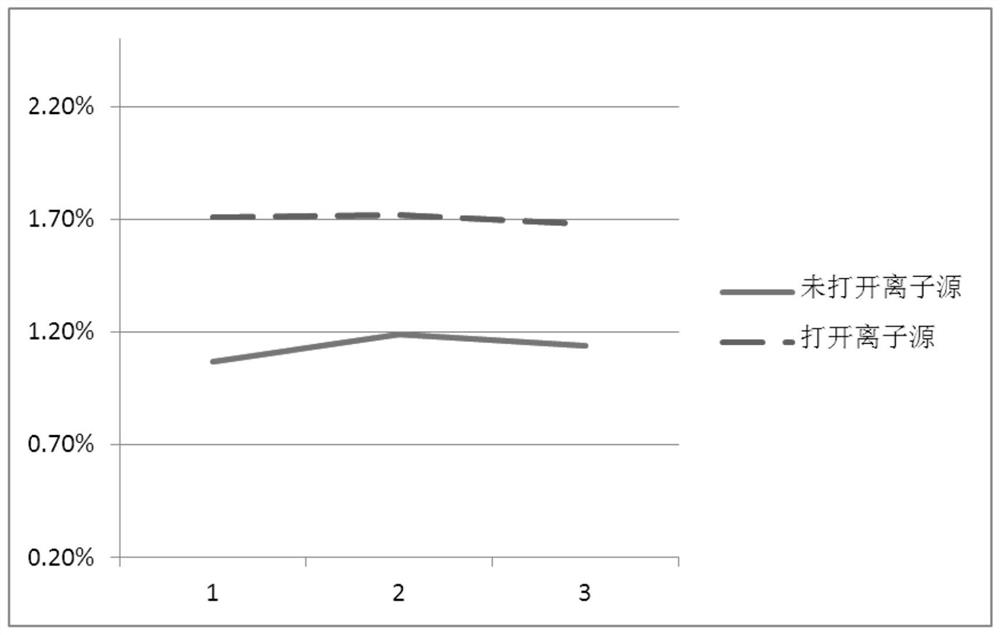
[0062] Step 5: Start sputtering NiFe according to the parameters set in Step 4, and at the same time, turn on the high-energy ion source again so that the ion beam of the high-energy ion source irradiate...
Embodiment 2
[0064] The specific preparation process of Ta-NiFe-Ta is as follows;
[0065] Step 1. Use isopropanol to clean the silicon wafer with an ultrasonic cleaner, and fix the clean silicon wafer to the sample tray in the sputtering chamber;
[0066] Step 2. Use a molecular pump to draw a high vacuum to the sputtering chamber. When the vacuum degree is better than 8×10 -5 At Pa, argon with a purity of 99.999% is introduced;
[0067] Step 3: Turn on the high-energy ion source, the high-energy ion source cleans the silicon wafer, and turn off the high-energy ion source after the cleaning is completed;
[0068] Step 4, sputtering the first layer of Ta;
[0069] 4.1) Set the sputtering power to 60W, keep the working pressure at about 0.3Pa, set the bias voltage to 0V, keep the speed of the sample disc at 5r / min, and set the sputtering time to 37s;
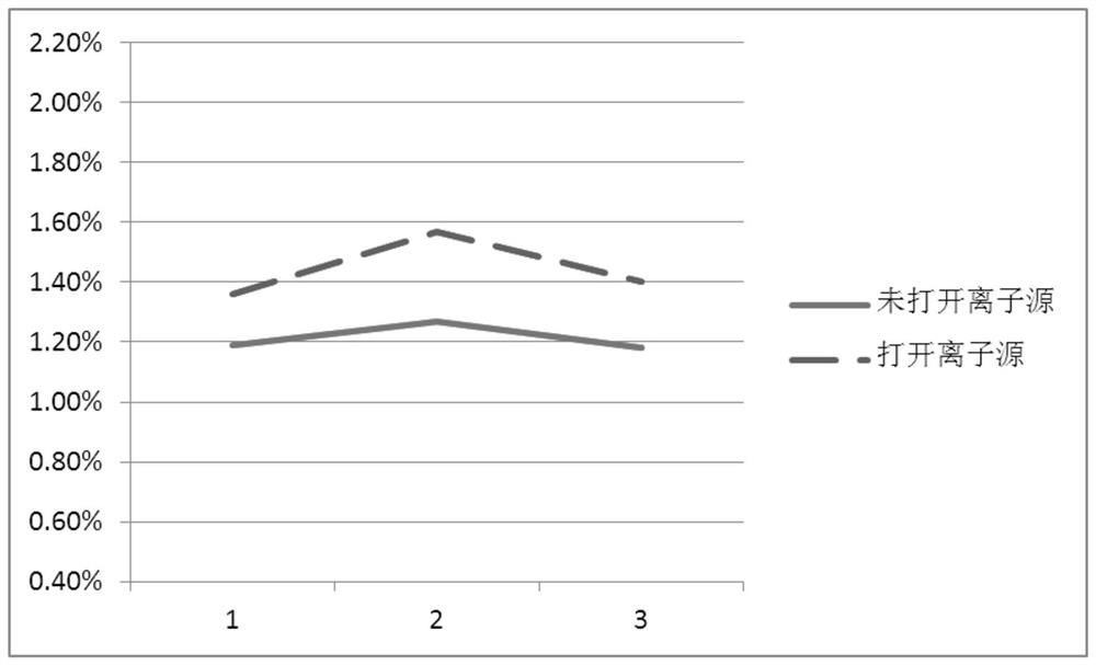
[0070] 4.2) Start sputtering Ta according to the parameters set in step 4.1), and at the same time, turn on the high-energy ion source ag...
PUM
 Abstract
Description
Claims
Application Information
 - Generate Ideas
- Intellectual Property
- Life Sciences
- Materials
- Tech Scout
- Unparalleled Data Quality
- Higher Quality Content
- 60% Fewer Hallucinations
Browse by: Latest US Patents, China's latest patents, Technical Efficacy Thesaurus, Application Domain, Technology Topic, Popular Technical Reports.
© 2025 PatSnap. All rights reserved.Legal|Privacy policy|Modern Slavery Act Transparency Statement|Sitemap|About US| Contact US: help@patsnap.com