
Gold foil dicing device

A technology of dicing and gold foil, applied in metal processing and other directions, can solve the problems of cumbersome, time-consuming, and low efficiency of square blocks, and achieve the effect of improving efficiency and facilitating cleaning

Inactive Publication Date: 2020-11-27
王浩然
View PDF6 Cites 3 Cited by
  • Summary
  • Abstract
  • Description
  • Claims
  • Application Information

AI Technical Summary

Problems solved by technology

[0004] In order to overcome the cumbersome process for workers to frequently change the cutting position of gold foil, it is inefficient for workers to cut a piece of gold foil into multiple square blocks at the same time, and it takes a long time for workers to clean up the excess gold foil corners Disadvantages, technical problems to be solved: Provide a method that does not require workers to frequently change the gold foil cutting position, and at the same time can cut a piece of gold foil into multiple square pieces, and does not require workers to manually clean up excess gold foil corners, thereby improving gold foil cutting. Block Efficient Gold Leaf Dicing Device

Method used


Image

  • Gold foil dicing device
  • Gold foil dicing device
  • Gold foil dicing device

Examples


Embodiment 1

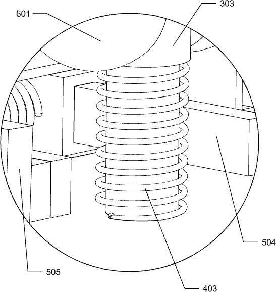
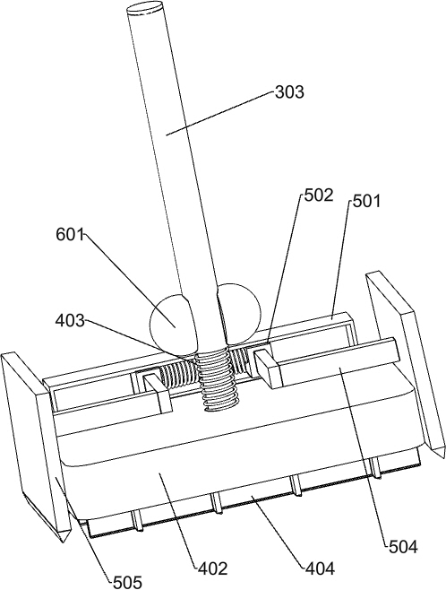
[0025] A gold leaf dicing device such as Figure 1-5 As shown, it includes a mounting frame 1, a placement plate 2, a swing mechanism 3 and a buffer mechanism 4. A placement plate 2 is connected between the tops of the mounting frame 1. The number of placement plates 2 is one, and a swing is installed on the rear side of the top of the placement plate 2. Mechanism 3, a buffer mechanism 4 is connected to the bottom of the swing mechanism 3.

[0026] When the worker needs to cut the gold leaf, the worker needs to put a piece of gold leaf on the sponge placement block body 7 first. The rotation will drive the buffer mechanism 4 to move downward, and the downward movement of the buffer mechanism 4 will cut the gold foil on the sponge placement block body 7, and then the worker needs to rotate the swing mechanism 3 clockwise, and the swing mechanism 3 will move upward to reset, and the swing mechanism The upward movement of 3 will drive the buffer mechanism 4 to move upward and re...

Embodiment 2

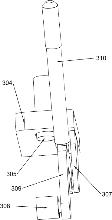
[0028] In a preferred embodiment of the present invention, as Figure 1-8 As shown, the swing mechanism 3 includes a mounting plate 301, a first guide sleeve 302, a first slide bar 303, a second guide sleeve 304, a second slide bar 305, a slide plate 306, an arc plate 307, a roller 308, and a Y-shaped pressing plate 309 And the pressure handle 310, the mounting plate 301 is welded in the middle of the top rear side of the mounting frame 1, the number of the mounting plate 301 is one, the first guide sleeve 302 is installed on the lower part of the front side of the mounting plate 301, the number of the first guide sleeve 302 is one, The first guide sleeve 302 is slidingly provided with a first slide bar 303, the number of the first slide bar 303 is one, and the upper part of the front side of the mounting plate 301 is fixedly connected with a second guide sleeve 304, and the number of the second guide sleeve 304 is One, the second slide bar 305 is provided slidingly in the sec...


PUM


Abstract

The invention relates to a dicing device, in particular to a gold foil dicing device. According to the gold foil dicing device, workers do not need to frequently change gold foil cutting positions, one piece of gold foil can be cut into a plurality of square blocks through one-time reciprocating, and the workers do not need to manually clean redundant gold foil corners, so that the gold foil dicing efficiency is improved. According to the technical scheme, the gold foil dicing device comprises mounting frames, a placing plate and the like, wherein the placing plate is connected between the tops of the mounting frames. A buffer mechanism moves up and down through a swing mechanism to cut a gold foil on a sponge containing block body into blocks, so that time and labor are saved. A blade moves downwards to make contact with the gold foil through the buffer mechanism, so that the gold foil dicing efficiency is improved. Leftover materials on the sponge placing block body can be rapidly shifted outwards through a shifting mechanism, so that workers can clean the leftover materials conveniently.

Description

technical field [0001] The invention relates to a cutting device, in particular to a gold foil cutting device. Background technique [0002] At present, most of the gold foil is generally made of thin sheets hammered from gold. Because gold has good ductility and plasticity, after the gold foil manufacturers make the whole piece of gold foil, the workers usually use tools to cut the whole piece of gold foil into square pieces of suitable size. , the worker needs to use a knife to cut a few cuts on the gold leaf on the sponge block, and then the worker needs to rotate the sponge block. The purpose of the worker rotating the sponge block is to change the cutting position of the gold leaf. After the worker has changed the cutting position of the gold leaf , the worker needs to use the cutter again to cut out several other cut marks on the gold foil on the sponge block, and the worker needs to manually clean up the excess gold foil corners on the sponge block. After the worker m...

Claims


Application Information

Patent Timeline
Patent Type & Authority Applications(China)
IPC IPC(8): B26D3/20B26D7/18
CPCB26D3/185B26D3/20B26D7/1818
Inventor 王浩然
Owner 王浩然
Learn More