Special clamp for cylindrical workpiece

A special fixture, cylindrical technology, applied in the direction of manufacturing tools, metal processing machinery parts, clamping, etc., can solve the problems of affecting the machining accuracy, pinching the workpiece, reducing the clamping force, etc., to improve the fastening effect, prevent The effect of clamping the workpiece and ensuring stability

Active Publication Date: 2020-11-27
ZHEJIANG GINT VACUUM FLASK TECH CD LTD
View PDF11 Cites 5 Cited by
  • Summary
  • Abstract
  • Description
  • Claims
  • Application Information

AI Technical Summary

Problems solved by technology

[0004] For workpieces with a cylindrical structure, in machining, the traditional triangular chuck is generally used to clamp the inner or outer circle of the workpiece; but for thinner workpieces, no matter whether it is through the outer Whether it is circular clamping or inner circle clamping, if the clamping force is not properly controlled, the workpiece may be clamped; it will affect the appearance and the later work, but in order to prevent the clamping of the workpiece, if the clamping force is reduced, the high-speed movement of the workpiece During the process, there will be a phenomenon of falling off, accidentally injuring the machine or the staff
[0005] The existing technology will use a layer of gaskets with equal thickness on the inner or outer circle of the workpiece, but this will easily cause the workpiece to slip due to friction on the one hand, and on the other hand, if the gasket is worn, the axis of the workpiece will be out of alignment. The misalignment of the axis of the fixture affects the machining accuracy

Method used


Image

  • Special clamp for cylindrical workpiece
  • Special clamp for cylindrical workpiece
  • Special clamp for cylindrical workpiece

Examples


Embodiment Construction

[0047] The specific implementation manners of the present invention will be further described in detail below in conjunction with the accompanying drawings and embodiments. The following examples or drawings are used to illustrate the present invention, but not to limit the scope of the present invention.

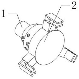
[0048] Such as figure 1 As shown, it includes an intermediate fixture 1 and an execution fixture 2, wherein the execution fixture 2 is connected with the inherent fixture on the machine tool through the intermediate fixture 1.

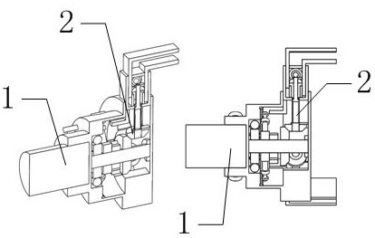
[0049] Such as figure 1 , 2 , 3, the above-mentioned execution fixture 2 includes the execution fixture housing 4, a claw mechanism 27, wherein as Figure 10 As shown, three claw mechanisms 27 evenly distributed in the circumferential direction are slidably installed on the front end of the housing of the execution fixture 2; The fourth gear 32 in the execution fixture housing 4 is meshed; the execution fixture housing 4 is also equipped with a ...


PUM


Abstract

The invention belongs to the technical field of clamps, and particularly relates to a special clamp for a cylindrical workpiece. The special clamp comprises a middle clamp and an execution clamp, wherein the execution clamp is connected with an inherent clamp on a machine tool through the middle clamp. The clamp designed by the invention can be suitable for the cylindrical workpiece with a small thickness, and the inner wall and the outer wall of the workpiece are fixed at the same time through three inner clamping plates and three outer clamping plates in a using process, so that the fastening effect can be improved; and under the condition of the same fastening effect, the clamping force of the clamp on the workpiece can be relatively reduced, so that the situation that the workpiece isdamaged by clamping is prevented to a certain extent. Three fastening mechanisms are designed in the special clamp, and after three mounting shells are fixed relative to the position of an execution clamp shell, the three mounting shells play a role in fixing and limiting through the three fastening mechanisms, so that the stability of the clamp for clamping the workpiece is guaranteed.

Description

[0001] Technical field [0002] The invention belongs to the technical field of fixtures, in particular to a special fixture for cylindrical workpieces. Background technique [0003] Fixtures refer to fixtures used to process workpieces in machining. [0004] For workpieces with a cylindrical structure, in machining, the traditional triangular chuck is generally used to clamp the inner or outer circle of the workpiece; but for thinner workpieces, no matter whether it is through the outer Whether it is circular clamping or inner circle clamping, if the clamping force is not properly controlled, the workpiece may be clamped; it will affect the appearance and the later work, but in order to prevent the clamping of the workpiece, if the clamping force is reduced, the high-speed movement of the workpiece During the process, there will be a phenomenon of falling off, accidentally injuring the machine or the staff. [0005] The existing technology will use a layer of gaskets with e...

Claims


Application Information

Patent Timeline
Patent Type & Authority Applications(China)
IPC IPC(8): B23Q3/00
CPCB23Q3/00
Inventor 邱靖涛邱宇
Owner ZHEJIANG GINT VACUUM FLASK TECH CD LTD
Why Eureka
Try Eureka