
Servo valve for controlling an internal combustion engine injection

a technology of internal combustion engine and fuel injector, which is applied in the direction of fuel injecting pump, liquid fuel feeder, machine/engine, etc., can solve the problems of undesirable lifting and shutter “bounce” and achieve the effect of reducing shutter “bounce” and shutter lift, reducing shutter “bounce” and reducing closing for

Active Publication Date: 2007-09-06
CENT RICERCHE FIAT SCPA
View PDF5 Cites 18 Cited by
  • Summary
  • Abstract
  • Description
  • Claims
  • Application Information

AI Technical Summary

Benefits of technology

[0010] It is an object of the present invention to provide a servo valve for controlling an internal combustion engine fuel injector, designed to solve the above problems in a straightforward, low-cost manner, and which preferably is easy to produce and assemble, is compact, and comprises a small number of components.
[0016] The above solution provides for a roughly 50% reduction in lift of the shutter, and a roughly 30% reduction in closing force; and the fact that the shutter is balanced assists in reducing “bounce” of the shutter.

Problems solved by technology

Known solutions as described above are unsatisfactory, on account of the characteristics and size of the shutter positioning spring having to be such as to exert a high preload, e.g. of about 70 newtons, to keep the outlet hole closed at high pressure (even as high as 1800 bars), so that powerful actuators are also required.
Because of the smaller sealing area, however, discharge of the control volume to activate the injection nozzle calls for relatively high lift (about 50 microns) of the shutter to uncover large enough flow sections, which lift is undesirable.
Moreover, a strong closing force of the shutter and direct axial exposure of the shutter to high pressure cause “bounce” of the shutter when closing.

Method used


Image

  • Servo valve for controlling an internal combustion engine injection
  • Servo valve for controlling an internal combustion engine injection
  • Servo valve for controlling an internal combustion engine injection

Examples


Embodiment Construction

[0020] Referring now to the drawings, wherein like reference numerals designate identical or corresponding parts throughout the several views.

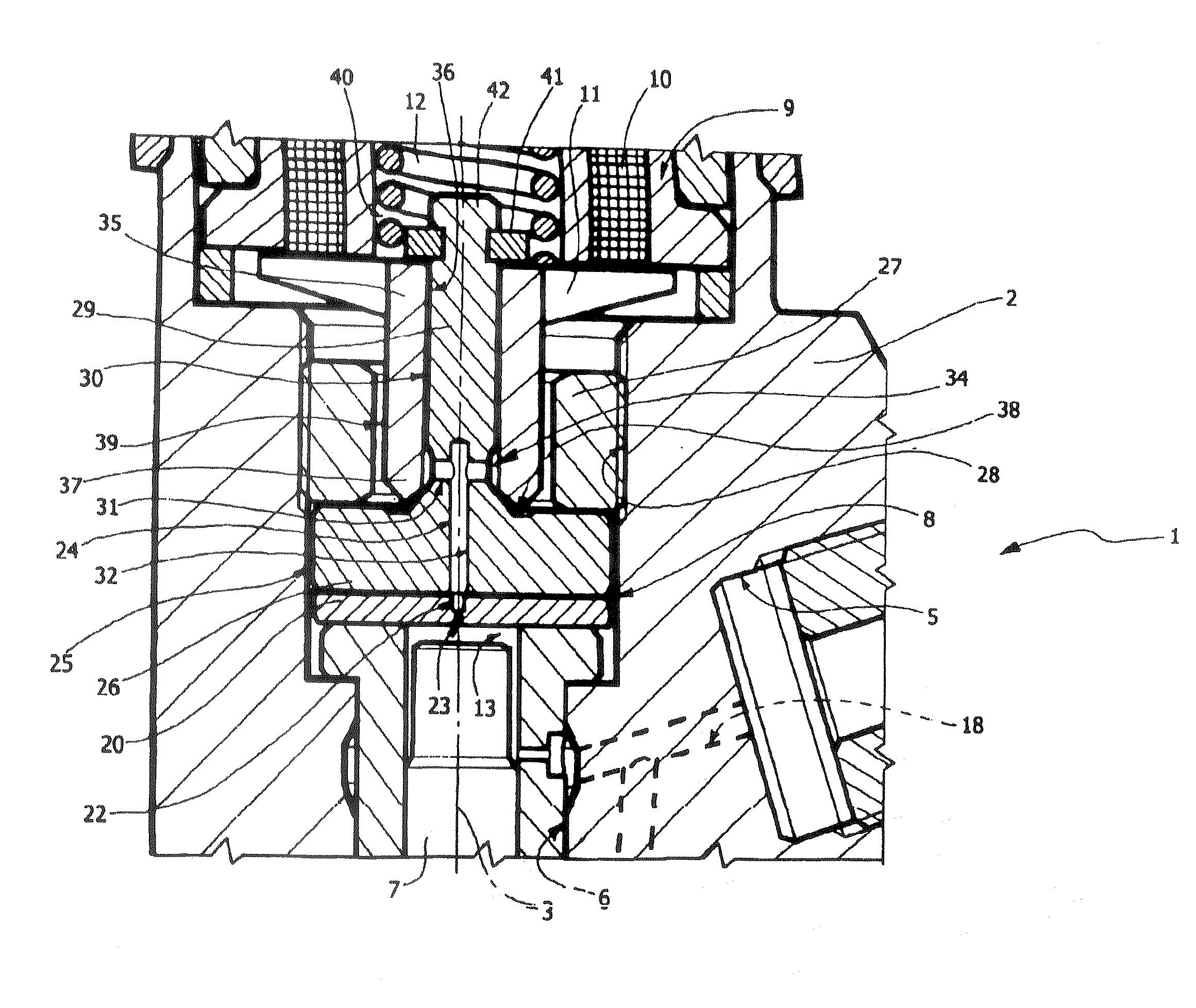
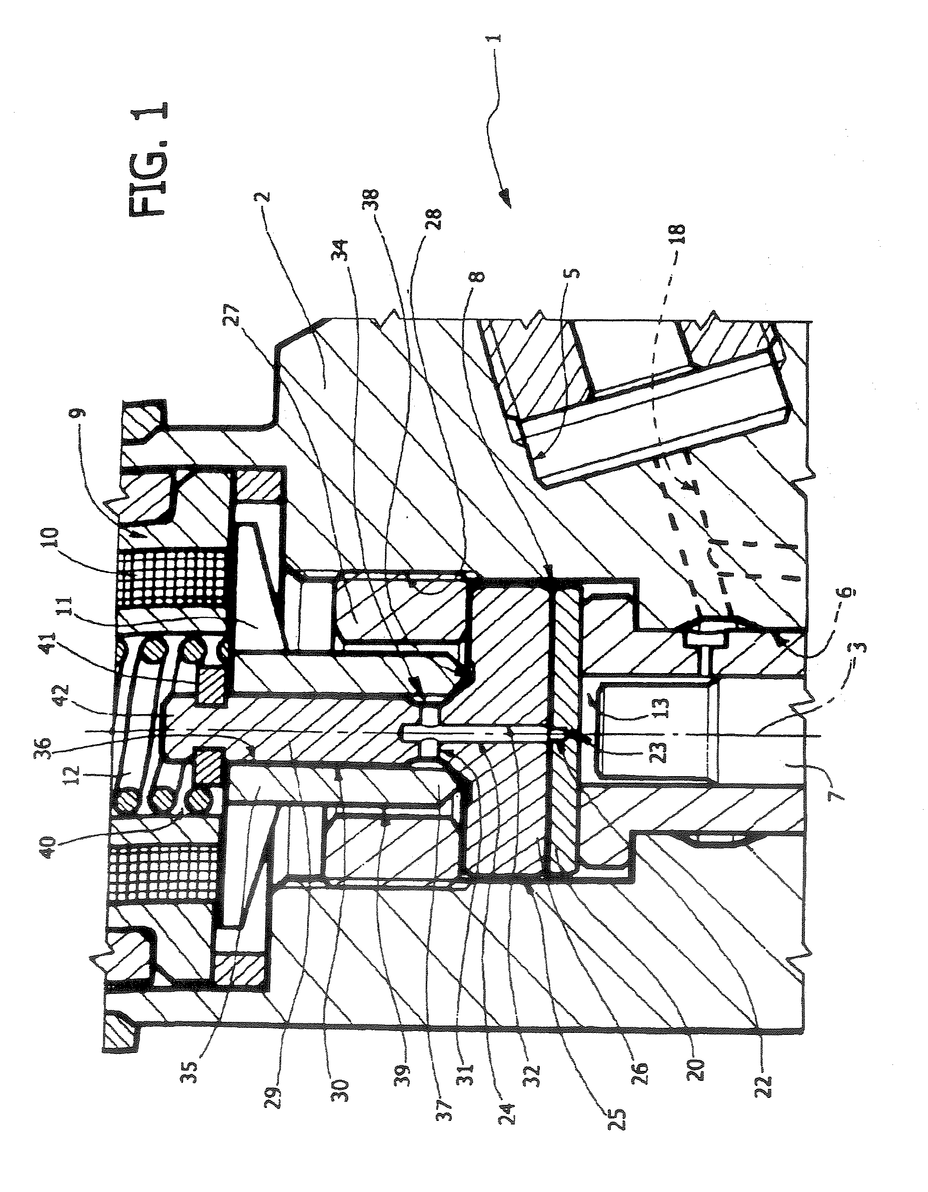
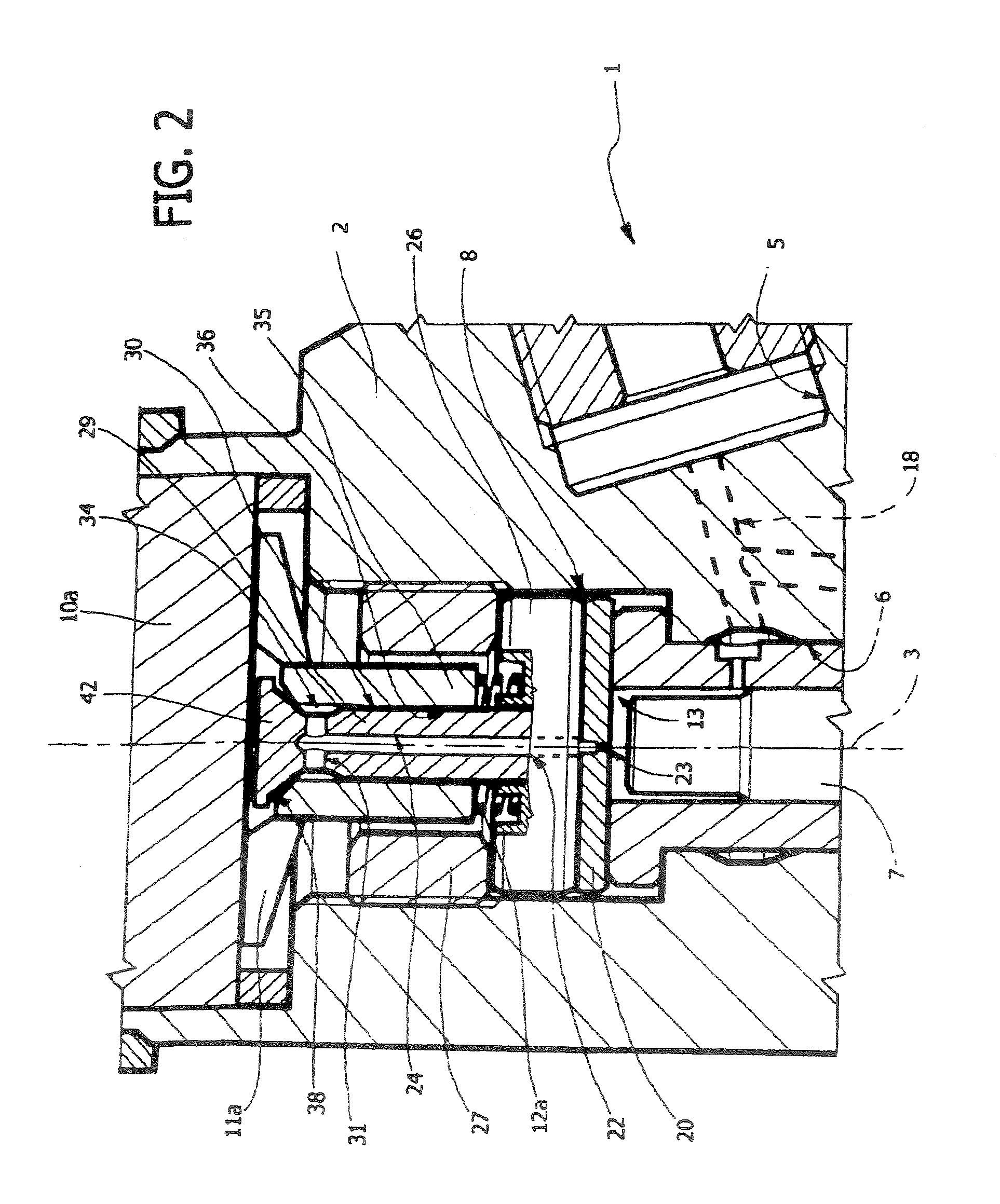
[0021] Number 1 in FIG. 1 indicates as a whole a fuel injector (shown partly) of an internal combustion engine, in particular a diesel engine (not shown). Injector 1 comprises an outer structure or casing 2 which extends along a longitudinal axis 3, has a lateral inlet 5 for connection to a pump forming part of a fuel feed system (not shown), and terminates with a nozzle (not shown) communicating with inlet 5 and for injecting fuel into a relative cylinder of the engine.

[0022] Casing 2 defines an axial seat 6, and houses a rod 7 which slides axially and in fluidtight manner inside seat 6 to control a shutter pin (not shown) for closing and opening the fuel injection nozzle.

[0023] Casing 2 houses a control servo valve 8 comprising an actuating device 9, which is coaxial with rod 7 and comprises an electromagnet 10; a segmental armature 11 wh...


PUM


Abstract

A control servo valve is housed inside the casing of an internal combustion engine fuel injector, and has an actuator, a control chamber communicating with a fuel inlet and with a fuel outlet passage, and a shutter movable along an axis by the actuator between a closed position and an open position to close and open the outlet passage respectively; the servo valve also has a fixed axial rod interposed between the actuator and the control chamber; the outlet passage comes out through an outer lateral surface of the axial rod; and the shutter is defined by a sleeve which slides axially on the outer lateral surface, and, in the closed position, closes the outlet passage so as to be subjected to a zero axial resultant force by the pressure of the fuel.

Description

CROSS-REFERENCE TO RELATED APPLICATIONS [0001] This application is a Continuation of and claims the benefit of priority under 35 U.S.C. §120 from U.S. Ser. No. 11 / 112,772, filed Apr. 21, 2005, and claims the benefit of Priority under 35 U.S.C. §119 from European Application No. 04425475.3, filed Jun. 30, 2004, the entire contents of which are incorporated herein by reference. BACKGROUND OF THE INVENTION [0002] 1. Field of the Invention [0003] The present invention relates to a servo valve for controlling an internal combustion engine fuel injector. [0004] 2. Description of the Related Art [0005] As is known, an injector comprises an injector body which defines a nozzle for injecting fuel into the engine, and houses a control rod movable along a respective axis to activate a pin closing the nozzle. The injector body also houses an electromagnetic control servo valve comprising a control chamber bounded axially on one side by the control rod, and on the other by an end wall having a c...

Claims


Application Information

Patent Timeline
Patent Type & Authority Applications(United States)
IPC IPC(8): F02M41/16F02M47/02F02M59/46
CPCF02M47/027F02M63/0015F02M63/004F02M63/0043F02M2547/003F02M63/0073F02M63/008F02M2200/28F02M63/0071
Inventor RICCO, MARIODE MATTHAEIS, SISTO LUIGIGORGOGLIONE, ADRIANODI MEO, ALFONSO
Owner CENT RICERCHE FIAT SCPA
Learn More