Identification method, device and equipment for effective scanning range of CT scanning bed and storage medium

A scanning range and CT scanning technology, applied in the field of CT scanning, can solve the problems of waste of medical resources, incompleteness, huge differences, etc., and achieve the effect of making full use of medical resources, improving scanning efficiency, and avoiding the increase of radiation.

Active Publication Date: 2020-11-27
PEKING UNIV SHENZHEN HOSPITAL
View PDF12 Cites 1 Cited by
  • Summary
  • Abstract
  • Description
  • Claims
  • Application Information

AI Technical Summary

Problems solved by technology

In addition, the actual image imaging range of CT scanning varies greatly depending on the scanning mode, collimation layer thickness, gantry rotation time, and pitch. If the image cannot be imaged or the image is incomplete outside the effective scanning range, it is necessary to adjust the position of the patient on the scanning table and re-scan the positioning image. For example, when scanning the patient's head, if the patient's head is too close to the starting end of the scanning table , the scan cannot completely cover the entire head. In this way, the position of the patient on the scanning bed may need to be adjusted multiple times during the scan, which reduces the efficiency of CT scanning, wastes medical resources, and the patient is exposed to radiation from multiple scans. And other issues

Method used


Image

  • Identification method, device and equipment for effective scanning range of CT scanning bed and storage medium
  • Identification method, device and equipment for effective scanning range of CT scanning bed and storage medium
  • Identification method, device and equipment for effective scanning range of CT scanning bed and storage medium

Examples


Embodiment Construction

[0054] Embodiments of the present invention are described in detail below, examples of which are shown in the drawings, wherein the same or similar reference numerals designate the same or similar elements or elements having the same or similar functions throughout. The embodiments described below by referring to the figures are exemplary only for explaining the present invention and should not be construed as limiting the present invention.

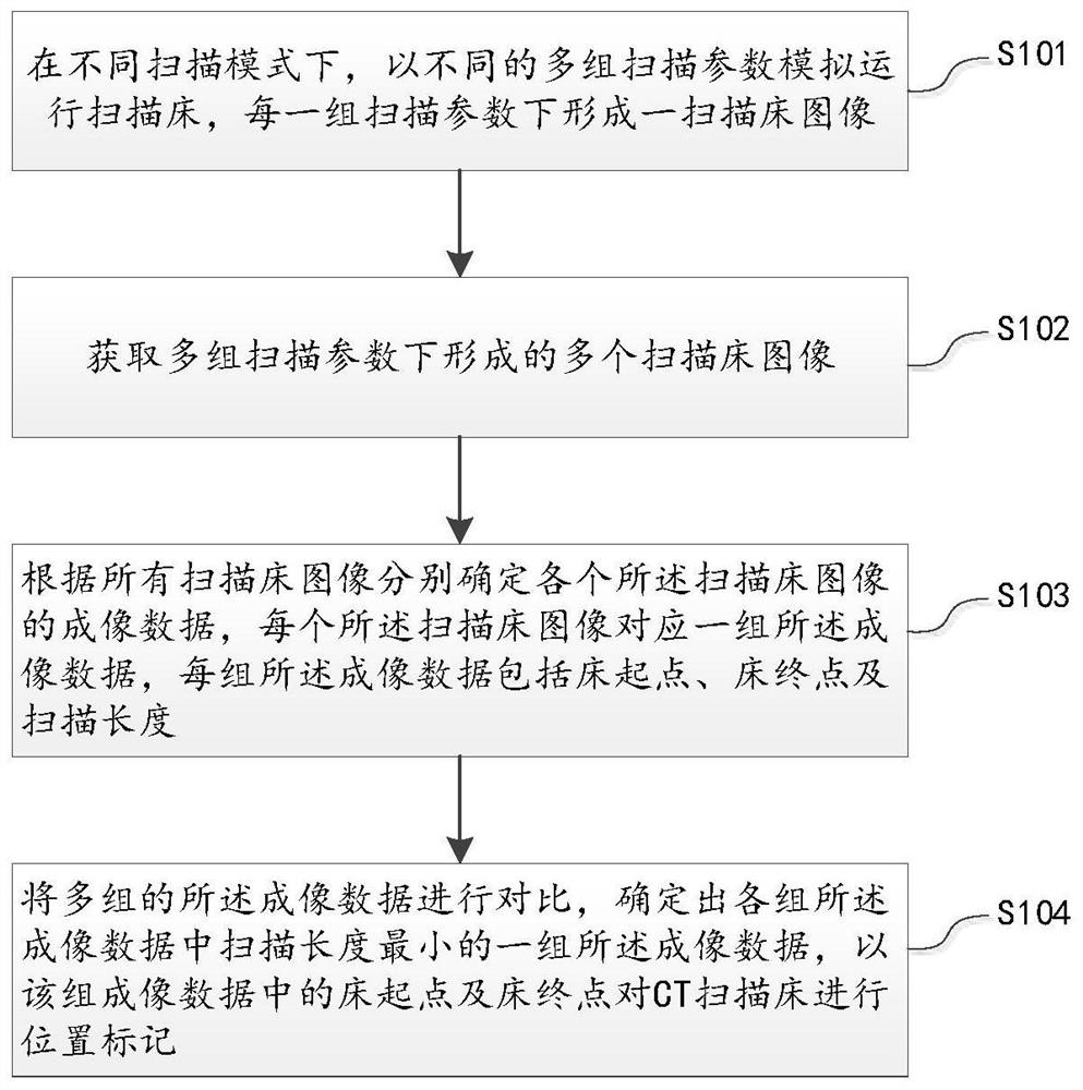
[0055] refer to figure 2 as shown, figure 2 A flowchart of an embodiment of a method for identifying an effective scanning range of a CT scanning table provided by an embodiment of the present invention is shown. For ease of description, only parts related to the embodiment of the present invention are shown. The method for identifying the effective scanning range of the CT scanning table specifically includes:

[0056] S101. Under different scanning modes, simulate the operation of the scanning couch with different sets of scanning ...


PUM


Abstract

The invention discloses an identification method, device and equipment for an effective scanning range of a CT scanning bed and a storage medium. The identification method comprises the steps that thesimulated operation of the scanning bed is carried out through a plurality of different groups of scanning parameters in different scanning modes, and a scanning bed image is formed under each groupof scanning parameters; a plurality of scanning bed images formed under a plurality of groups of simulation parameters are obtained; imaging data of each scanning bed image is correspondingly determined according to all the scanning bed images, each scanning bed image corresponds to a group of imaging data, and each group of imaging data comprises a bed starting point, a bed end point and a scanning length; and the multiple groups of imaging data are compared, a group of imaging data with the smallest scanning length in each group of imaging data is determined, and the position of the CT scanning bed is marked according to the bed starting point and the bed end point in the group of imaging data. According to the identification method for the effective scanning range CT of the CT scanningbed, the scanned effective scanning range can be marked, the scanning efficiency can be improved, and medical resources are fully utilized; and meanwhile, the problem of repeated scanning radiation ofa patient is solved.

Description

technical field [0001] The present invention relates to the technical field of CT scanning, in particular to a method, device, equipment and storage medium for marking the effective scanning range of a CT scanning bed. Background technique [0002] CT (Computed Tomography), that is, computerized tomography, uses a precisely collimated X-ray beam and a highly sensitive detector to continuously rotate around a certain part of the human body and collect information to reconstruct multiple cross-sectional images of the part. , has the characteristics of fast scanning time, clear images without overlapping, etc., and can be used for the examination of various diseases. [0003] During CT scanning, the patient lies on the scanning bed without moving, and the patient on the scanning bed is scanned by using the movement of the scanning bed and the continuous rotation of the tube detector. During the scanning process, the scanning bed needs to be accelerated from a static state to a ...

Claims


Application Information

Patent Timeline
Patent Type & Authority Applications(China)
IPC IPC(8): A61B6/03A61B6/04G06T11/00
CPCA61B6/032A61B6/0407G06T11/005
Inventor 袁知东
Owner PEKING UNIV SHENZHEN HOSPITAL
Why Eureka
Try Eureka