
Radar antenna array structure with low sidelobe

A radar antenna and array structure technology, which is applied to antenna arrays, antennas, radiation unit housings, etc., can solve the problems that radar cannot meet low side lobes, lack of reduction of radar antenna belt feeder side lobes, etc., to improve side lobe performance, reduce Radiation, the effect of reducing side lobes

Inactive Publication Date: 2020-11-24
HUIZHOU DESAY SV INTELLIGENT TRANSPORTATION TECH INST CO LTD
View PDF7 Cites 0 Cited by
  • Summary
  • Abstract
  • Description
  • Claims
  • Application Information

AI Technical Summary

Problems solved by technology

Existing radars cannot meet the requirements of low side lobes. The current method of reducing radar antenna side lobes is mainly to reduce the side lobes of the single line array, but there is no solution to reduce the side lobes after the radar antenna belt feeder

Method used


Image

  • Radar antenna array structure with low sidelobe
  • Radar antenna array structure with low sidelobe
  • Radar antenna array structure with low sidelobe

Examples


Embodiment Construction

[0029] In order to facilitate the understanding of the present invention, the present invention will be described more fully below with reference to the associated drawings. Preferred embodiments of the invention are shown in the accompanying drawings. However, the present invention can be embodied in many different forms and is not limited to the embodiments described herein.

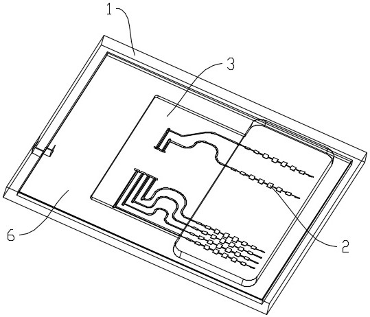
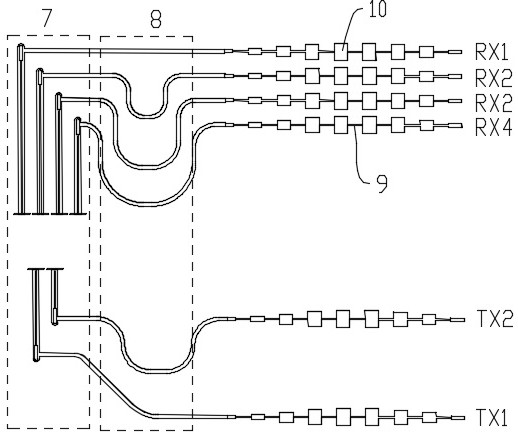
[0030] Such as Figure 1 to Figure 5 As shown, in a preferred embodiment, the radar antenna array structure with low sidelobe of the present invention mainly includes a radome 1 and an antenna 2 , and the radome 1 is set above the antenna 2 .

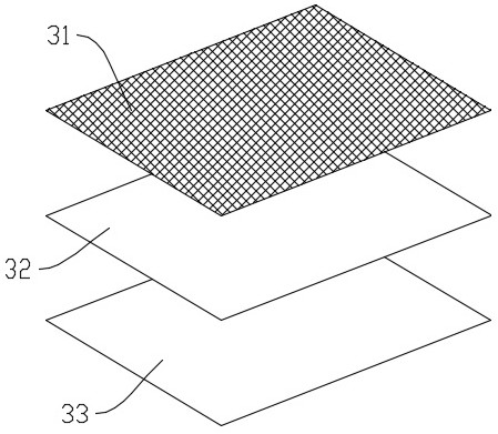
[0031] Wherein, the inner surface of the radome 1 is provided with a metamaterial wave-absorbing material 3 . It should be understood that the metamaterial wave-absorbing material 3 is a material with a wave-absorbing function formed by etching a special shape above the PCB board. The metamaterial absorbing material 3 includes a stacked metamaterial layer 31 ...


PUM


Abstract

The invention relates to a radar antenna array structure with low sidelobe. The structure comprises a radome and an antenna, and the antenna cover covers the upper part of the antenna. The inner surface of the radome is provided with a metamaterial wave-absorbing material. The metamaterial wave-absorbing material comprises a metamaterial layer, a middle dielectric layer and a reference ground layer which are arranged in a stacked mode, the reference ground layer is attached to the inner wall of the radome, the metamaterial layer faces the antenna, the metamaterial layer comprises a plurality of metamaterial units, and the metamaterial units are arranged periodically. The sidelobe performance of the radar antenna can be improved while the working frequency, the working bandwidth and the gain of the radar antenna are not affected.

Description

technical field [0001] The invention relates to the technical field of antennas, in particular to a radar antenna array structure with low sidelobe. Background technique [0002] As one of the most important sensors in the field of automotive active safety, millimeter-wave radar has the characteristics of strong ability to penetrate fog, smoke, and dust, and can work all-day and all-weather. With the current level of automotive automation and intelligence increasing, and consumers' pursuit of higher vehicle safety, millimeter-wave radars are increasingly used in vehicles, especially self-driving vehicles. [0003] At present, the entire industry has invested a lot of manpower and material resources in the 77GHz radar, but because the signal processing has special requirements for the radar antenna layout and the phase between the radar transmitting and receiving antennas, in order to meet these requirements, generally in the Specific processing on the radar traces, such as ...

Claims


Application Information

Patent Timeline
Patent Type & Authority Applications(China)
IPC IPC(8): H01Q1/42H01Q15/00H01Q17/00H01Q21/00
CPCH01Q1/42H01Q15/0086H01Q17/008H01Q21/00
Inventor 李权孙靖虎曾迪叶秀美王昆鹏
Owner HUIZHOU DESAY SV INTELLIGENT TRANSPORTATION TECH INST CO LTD
Learn More