
Geometry-Shaping Microwave Resonators

A resonator and microwave technology, used in resonators, waveguide-type devices, circuits, etc., can solve problems such as electromagnetic compatibility of external circuits, reduce the complexity of processing and assembly, expand the range of parasitic resonance frequencies, and improve processing. The effect of increased flexibility and process compatibility

Active Publication Date: 2021-07-16
SHENZHEN UNIV
View PDF7 Cites 0 Cited by
  • Summary
  • Abstract
  • Description
  • Claims
  • Application Information

AI Technical Summary

Problems solved by technology

However, this will generate electromagnetic radiation in the upper stop band of the filter, which will bring electromagnetic compatibility problems to the external circuit, and is not conducive to the communication system to suppress external interference signals in the upper stop band

Method used


Image

  • Geometry-Shaping Microwave Resonators
  • Geometry-Shaping Microwave Resonators
  • Geometry-Shaping Microwave Resonators

Examples


Embodiment 1

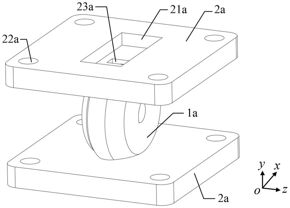
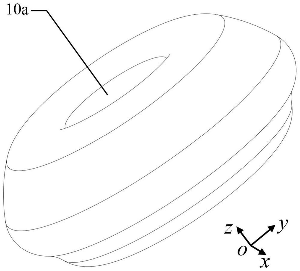
[0040] see figure 1 and figure 2 , figure 1 A three-dimensional structure diagram of a geometrically shaped microwave resonator provided in Embodiment 1 of the present invention. In Embodiment 1 of the present invention, the geometrically shaped microwave resonator includes a metal shell 1a and two waveguide flanges 2a, two coupling windows 23a are symmetrically opened on the metal shell 1a, and the two waveguide flanges 2a They are respectively arranged at two coupling windows 23a, and the waveguide flange 2a is provided with a feeding rectangular waveguide 21a communicating with the coupling window 23a. The setting of the two feeding rectangular waveguides 21a and the two coupling windows 23a can realize the The plastic resonant cavity 10a inside the body 1a performs two-port weak coupling feeding. Wherein, the plastic resonant cavity 10a is filled with air, and the metal shell 1a is made of metal, or is made of other insulating materials coated with a metal layer on the...

Embodiment 2

[0052] see Figure 6 and Figure 7 , Figure 6 A perspective view of a geometrically shaped microwave resonator provided in Embodiment 2 of the present invention, Figure 7 A cross-sectional view of the plastic resonant cavity 10b provided in Embodiment 2 of the present invention. The difference between the second embodiment and the first embodiment is that the size of the shaped resonant cavity 10b in the second embodiment is scaled down in the direction of the y axis, so that the cross section of the shaped resonant cavity 10a on the xoy plane is elliptical, namely The shaped resonant cavity 10b in the second embodiment can be equivalently considered to be shaped by an elliptical hemispherical cavity. The ratio of the short axis to the long axis of the elliptical hemispherical cavity is 0.5 to 1, and the shorter the short axis of the elliptical hemispherical cavity, the lower the unloaded Q value. In the direction of the ox axis, the dimensions of the irregular resonant ...


PUM


Abstract

The invention provides a geometrically shaped microwave resonator, which includes a metal shell and two waveguide flanges. The metal shell has a shaped resonant cavity. After shaping the hemisphere and the second shaping hemisphere, the inner wall of the hemispherical cavity includes a radial section and a hemispherical surface connected to the radial section, and the radial section is perpendicular to the end face where the rectangular waveguide port of the waveguide flange is located. The torus is formed by indenting the circumference of the radial section to the interior of the hemispherical cavity, the first plastic hemisphere is formed by indenting the hemisphere facing the interior of the hemispherical cavity, and the second shaping hemisphere is formed by indenting the interior of the hemispherical cavity from the radial section As a result, the cavity wall of the shaped resonant cavity is set smoothly. The geometrically shaped microwave resonator provided by the present invention satisfies the requirements of high Q value, far parasitic resonance and no radiation in the upper stop band at the same time through the geometric shaping method, and significantly improves the impact of the resonant cavity structure on subtractive manufacturing and additive manufacturing. Process compatibility of manufacturing technologies.

Description

technical field [0001] The invention belongs to the technical field of electromagnetic fields and microwaves, and in particular relates to a geometrically shaped microwave resonator. Background technique [0002] High quality factor (Q value) and far spurious resonant modes are the basic requirements for resonators in microwave filters of communication systems. The high-Q resonator can make the filter obtain smaller passband insertion loss under the same bandwidth. The far spurious resonance mode can make the upper stop band of the bandpass filter realize a wide bandwidth and high rejection, so as to reduce the influence of harmonics and interference signals in the stop band. Air-filled rectangular, cylindrical and spherical resonators are several commonly used high-Q cavity resonators. Among them, the spherical cavity has the highest Q value, but its higher-order mode is closer to the fundamental mode than the rectangular cavity. [0003] In the prior art, the goal of min...

Claims


Application Information

Patent Timeline
Patent Type & Authority Patents(China)
IPC IPC(8): H01P7/00
CPCH01P7/00
Inventor 李津陈哲袁涛
Owner SHENZHEN UNIV
Learn More