
Power correction circuit anomaly detection method, system and circuit

A technology of power correction and abnormal detection, applied in the direction of electric power measurement through current/voltage, measuring current/voltage, measuring devices, etc., can solve problems such as economic losses in production and life, data loss, unit tripping, etc., to achieve early prediction, The effect of preventing the spread of problems

Active Publication Date: 2020-11-24
INSPUR SUZHOU INTELLIGENT TECH CO LTD
View PDF2 Cites 4 Cited by
  • Summary
  • Abstract
  • Description
  • Claims
  • Application Information

AI Technical Summary

Problems solved by technology

The parameter drift of some components causes the power correction circuit of the power supply to work abnormally, and in some applications, it causes the abnormality of the whole server or the tripping of the upper-level power supply unit of the power supply
[0003] In the existing technology, the power supply alarm is usually reported after the power supply fails or the corresponding protection mechanism is triggered, or the positive and negative compensation is adjusted to confirm whether the inductance is offset. The above two methods cannot let the user know in advance that the power correction circuit has occurred. The work is abnormal. Once the power correction circuit is known to be working abnormally through the above method, the power correction circuit needs to be maintained immediately, resulting in an abnormality of the server or a trip of the upper-level power supply unit of the power supply, which may easily cause data loss and cause serious problems in production and life. economic loss

Method used


Image

  • Power correction circuit anomaly detection method, system and circuit
  • Power correction circuit anomaly detection method, system and circuit
  • Power correction circuit anomaly detection method, system and circuit

Examples


Embodiment Construction

[0036] The following will clearly and completely describe the technical solutions in the embodiments of the present invention with reference to the accompanying drawings in the embodiments of the present invention. Obviously, the described embodiments are only some, not all, embodiments of the present invention. Based on the embodiments of the present invention, all other embodiments obtained by persons of ordinary skill in the art without making creative efforts belong to the protection scope of the present invention.

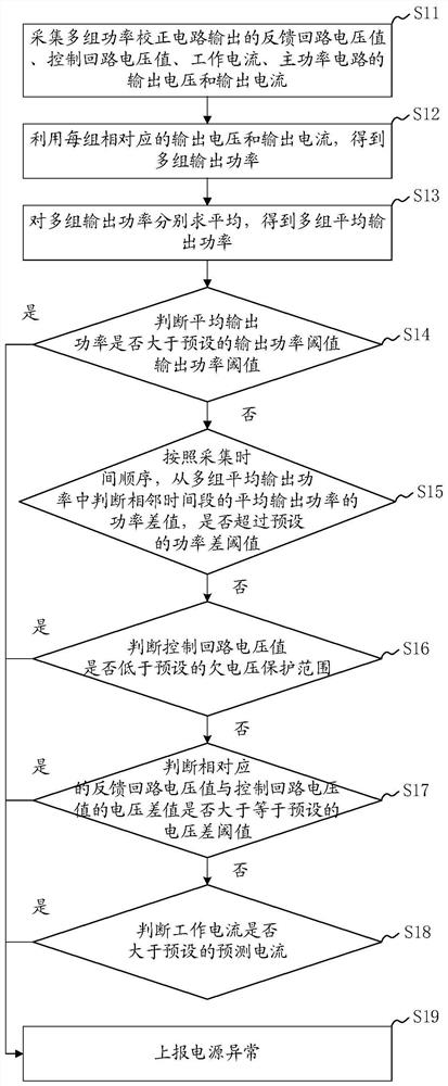
[0037] The embodiment of the present invention discloses a power correction circuit abnormality detection method, see figure 1 As shown, the method includes:

[0038] S11: Collect feedback loop voltage values, control loop voltage values, operating currents, output voltages and output currents of main power circuits output by multiple sets of power correction circuits.

[0039] Specifically, when controlling the power correction circuit, two loops, the feedba...


PUM


Abstract

The invention discloses a power correction circuit anomaly detection method, system and circuit. The method comprises the steps: collecting feedback loop voltage values, control loop voltage values and working currents outputted by multiple groups of power correction circuits and output voltages and output currents of a main power circuit; utilizing the output voltage and the output current corresponding to each group to obtain a plurality of groups of output power; averaging the multiple groups of output power to obtain average output power; when the average output power is smaller than a preset output power threshold value; if so, gradually judging whether the power outputted by the main power circuit and the voltage and current of the power correction circuit are in a normal range; whether the power correction circuit is abnormal due to device parameter drifting or not can be detected in advance, if the power correction circuit is abnormal, abnormal information can be reported as soon as possible, maintenance personnel are reminded to prepare for maintenance, early prediction of faults is achieved, it is ensured that a power source corresponding to the abnormal power correctioncircuit can be replaced in time, and problem diffusion is prevented.

Description

technical field [0001] The invention relates to the technical field of power electronics, in particular to a method, system and circuit for abnormality detection of a power correction circuit. Background technique [0002] With the rapid development of the Internet economy, massive data is impacting the entire data center industry with an unprecedented growth trend. A large number of data centers are under construction and put into use, and the demand for servers is huge. The parameter drift of some components causes the power correction circuit of the power supply to work abnormally, and in some applications, causes the abnormality of the whole server or the tripping of the upper-level power supply unit of the power supply. [0003] In the existing technology, the power supply alarm is usually reported after the power supply fails or the corresponding protection mechanism is triggered, or the positive and negative compensation is adjusted to confirm whether the inductance i...

Claims


Application Information

Patent Timeline
Patent Type & Authority Applications(China)
IPC IPC(8): G01R21/06G01R19/165
CPCG01R21/06G01R19/165
Inventor 陈玉堂
Owner INSPUR SUZHOU INTELLIGENT TECH CO LTD
Learn More