Spatial discrete multi-beam high-power laser time waveform measurement system

A space discrete, waveform measurement technology, applied in the direction of instruments, etc., can solve the problems of complex structure, high maintenance cost and high cost of pulse time waveform measurement system, and achieve the effect of simple structure, reduced maintenance cost and cost saving

Active Publication Date: 2020-11-24
XI'AN INST OF OPTICS & FINE MECHANICS - CHINESE ACAD OF SCI
View PDF11 Cites 0 Cited by
  • Summary
  • Abstract
  • Description
  • Claims
  • Application Information

AI Technical Summary

Problems solved by technology

[0003] The present invention aims to solve the technical problems in the prior art that the pulse time waveform measurement system has complex structure, high cost, many connections and high maintenance cost when there are many laser beams, and provides a spatially discrete multi-beam high-power laser time Waveform measurement system, couple multiple beams to one beam, and then measure the coupled beam light

Method used


Image

  • Spatial discrete multi-beam high-power laser time waveform measurement system
  • Spatial discrete multi-beam high-power laser time waveform measurement system
  • Spatial discrete multi-beam high-power laser time waveform measurement system

Examples


Embodiment Construction

[0022] In order to make the purpose, advantages and features of the present invention clearer, the spatially discrete multi-beam high-power laser time waveform measurement system proposed by the present invention will be further described in detail below in conjunction with the accompanying drawings and specific embodiments. The advantages and features of the present invention will be more clear from the following specific embodiments. It should be noted that: the drawings are all in a very simplified form and use inaccurate proportions, which are only used to facilitate and clearly illustrate the purpose of the embodiments of the present invention; secondly, the structures shown in the drawings are often actual structures part.

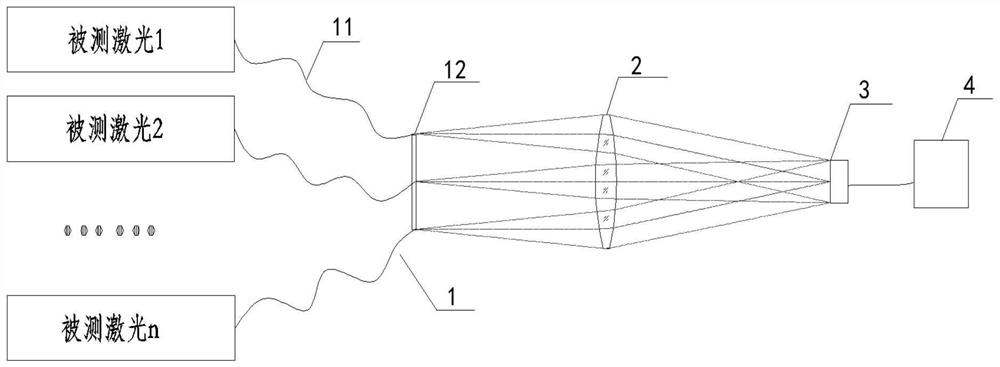
[0023] The present invention is a spatially discrete multi-beam high-power laser time waveform measurement system, such as figure 1 As shown, the system includes an optical fiber unit 1, a coupling objective lens 2, a detector 3, and an oscilloscope...


PUM


Abstract

The invention discloses a spatial discrete multi-beam high-power laser time waveform measurement system, and aims to solve the technical problems of complex structure, high cost, more wiring and highmaintenance cost of a pulse time waveform measurement system when more laser beams exist in the prior art. The system comprises an optical fiber unit, a coupling objective lens, a detector and an oscilloscope which are sequentially arranged along an optical path. The optical fiber unit comprises n beams of optical fibers, and n is a positive integer greater than or equal to 4. The incident end ofeach optical fiber bundle is connected with a measured light source, and the emergent end of each optical fiber bundle is provided with an optical fiber adapter. Ports of the optical fiber adapter interfaces are located in the same plane, and the plane is perpendicular to the optical axis of the coupling objective lens. The target surface of the detector is located at the exit pupil position of the coupling objective lens. The oscilloscope and the detector are electrically connected. The system has unique advantages for time waveform measurement of all-in-one laser beams in spatial discrete distribution.

Description

technical field [0001] The invention relates to a time waveform measurement system of light beams, in particular to a space discrete multi-beam high-power laser time waveform measurement system. Background technique [0002] In the measurement of multi-beam high-power laser parameters, the measurement of laser pulse time waveform generally adopts a one-to-one measurement method, that is, one beam of measured laser corresponds to one detector, and one detector corresponds to a high-speed and high-bandwidth oscilloscope channel. The next high-speed and high-bandwidth oscilloscope has four channels, that is, four detectors need to be equipped with a high-speed and high-bandwidth oscilloscope to measure the high-power laser time waveform. Both the detector and the high-speed and high-bandwidth oscilloscope are expensive instruments. , especially high-speed and high-bandwidth oscilloscopes are high-end equipment, and their cost is very high. When there are fewer laser beams, few...

Claims


Application Information

Patent Timeline
Patent Type & Authority Applications(China)
IPC IPC(8): G01J11/00
CPCG01J11/00
Inventor 李红光孙策达争尚董晓娜
Owner XI'AN INST OF OPTICS & FINE MECHANICS - CHINESE ACAD OF SCI
Why Eureka
Try Eureka