A radio frequency signal sensing device based on photoelectric oscillator

A radio frequency signal and sensing device technology, applied in the field of optoelectronics, can solve the problems of intermediate frequency signal power fluctuation, modulation efficiency and dynamic range change, bias point drift, etc., to achieve the effect of improving isolation, compact structure and mature manufacturing process

Active Publication Date: 2020-08-11
ZHEJIANG UNIV
View PDF5 Cites 0 Cited by
  • Summary
  • Abstract
  • Description
  • Claims
  • Application Information

AI Technical Summary

Problems solved by technology

Such as the literature "J.Zhang, F.Chen, and B.Sun,"Integrated Optical E-Field Sensor for IntenseNanosecond Electromagnetic Pulse Measurement"IEEE Photon.Technol.Lett.vol.26, no.3, pp.275-277. Jan, 2014.2. and T.Meier, C.Kostrzewa, K.Petermann and B.Schuppert, "Integrated optical E-field probes with segmented modulator electrodes" IEEE J.Lightw.Technol.vol.12, no.8, pp. The technical scheme proposed in 1497-1503,1994", in which the integrated optical electric field sensor is based on the Mach-Zehnder waveguide structure, and its bias point is prone to drift due to changes in the surrounding environment such as temperature and humidity, resulting in modulation efficiency and dynamic range changes, eventually leading to fluctuations in the power of the IF signal

Method used


Image

  • A radio frequency signal sensing device based on photoelectric oscillator
  • A radio frequency signal sensing device based on photoelectric oscillator
  • A radio frequency signal sensing device based on photoelectric oscillator

Examples


Embodiment Construction

[0031] In order to describe the present invention more specifically, the technical solutions of the present invention will be described in detail below in conjunction with the accompanying drawings and specific embodiments.

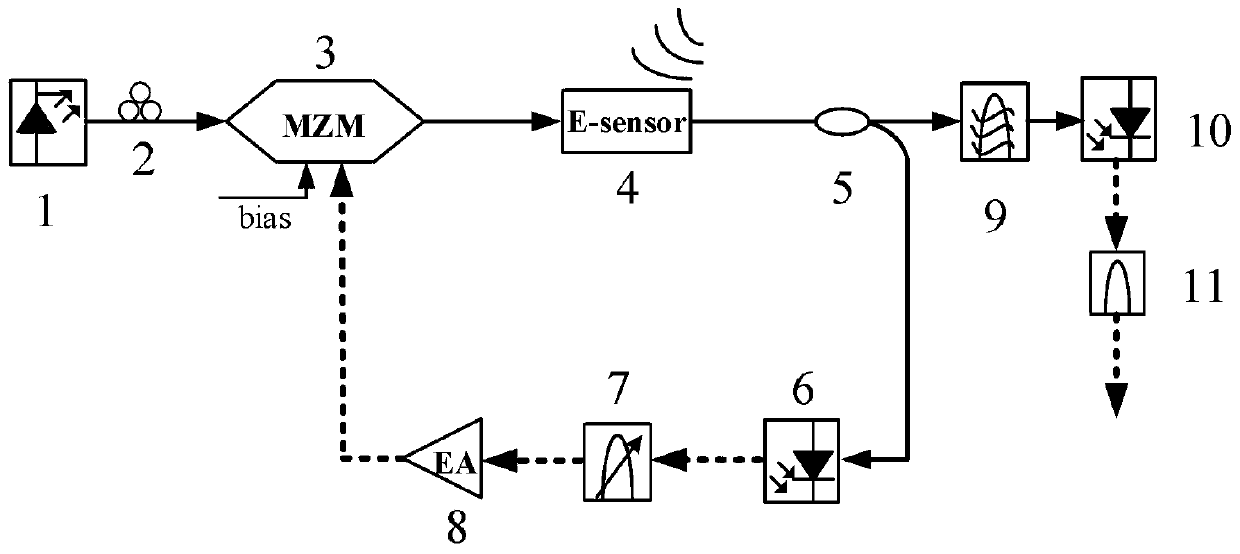
[0032] The radio frequency signal sensing device based on the photoelectric oscillator of the present invention such as figure 1 As shown, the device includes a laser source 1, a polarization controller 2, a Mach-Zehnder modulator 3, an electromagnetic field sensor 4, a fiber coupler 5, a photodetector 6, an adjustable radio frequency bandpass filter 7, a radio frequency amplifier 8, an optical Filter 9, photodetector 10, intermediate frequency bandpass filter 11.

[0033] Among them, the laser source 1, the polarization controller 2, the Mach-Zehnder modulator 3, the electromagnetic field sensor 4, the fiber coupler 5, and the photodetector 6 are sequentially connected through optical fibers; the photodetector 6, the adjustable radio frequency bandpass f...


PUM


Abstract

The present invention discloses a radio-frequency signal perception device based on a photoelectric oscillator. The device comprises a laser source, a polarization controller, a Mach-Zehnder modulator, an electromagnetic field sensor, an optical fiber coupler, an adjustable radio frequency band-pass filter, a radio-frequency amplifier, an optical filter, an intermediate-frequency band-pass filterand two photoelectric detectors; the laser source, the polarization controller, the Mach-Zehnder modulator, the electromagnetic field sensor and the photoelectric detectors are connected through optical fibers; radio frequency input ports of the photoelectric detectors, the optical fiber coupler, the adjustable radio frequency band-pass filter, the radio-frequency amplifier and the Mach-Zehnder modulator are connected in order; and one output of the optical fiber coupler, the optical fiber, the photoelectric detectors and the intermediate-frequency band-pass filter are connected in order. Theradio-frequency signal perception device achieves intermediate-frequency receiving of the high-frequency broadband electromagnetic field, reduce the cost of receiving the high-frequency device, does not need an external local oscillator, and is simple in electromagnetic sensor structure and good in radio-frequency signals to be received and the isolation of the local oscillator.

Description

technical field [0001] The invention belongs to the technical field of optoelectronics, and in particular relates to a radio frequency signal sensing device based on a photoelectric oscillator. Background technique [0002] With the urgent need for high-speed communication, high-frequency and broadband spectrum resources are fully utilized, and the signal frequency bands carrying various information cover a wide range and complex signal parameters. The highly dense and complex signal environment requires the receiver of electronic equipment to have large receiving bandwidth, large dynamic range, high efficiency, high resolution, and the ability to receive and process multi-frequency and multi-form signals in a unified manner. Traditional electrical receivers face the shortcomings of narrow bandwidth and large link loss, and their ability to receive and process high-frequency broadband signals has been greatly limited. [0003] Photonics technology has the advantages of high...

Claims


Application Information

Patent Timeline
Patent Type & Authority Patents(China)
IPC IPC(8): H04B10/60H04B10/61H04B10/556
CPCH04B10/5561H04B10/60H04B10/6151
Inventor 金晓峰肖康金向东余显斌沈小青丛波
Owner ZHEJIANG UNIV
Why Eureka
Try Eureka