High-reliability electromagnetic power-off brake

An electromagnetic power loss and reliability technology, applied in the direction of brake type, axial brake, brake actuator, etc., can solve the problems of small contact surface, failure, poor braking performance of electromagnetic power loss brake, etc., and achieve volume and Small weight, fast response, good braking performance

Active Publication Date: 2020-11-24
ZHEJIANG INNUOVO HERTZ ELECTRIC CO LTD +1
View PDF9 Cites 2 Cited by
  • Summary
  • Abstract
  • Description
  • Claims
  • Application Information

AI Technical Summary

Problems solved by technology

[0003] Most of the existing electromagnetic brakes fix the friction plate on the surface of the brake disc. When the electromagnetic de-energized brake of this structure is assembled with the rotor, especially the outer rotor of the motor, it may be due to the machining accuracy of the matching part of the rotor and the brake disc. After the moving disc and the rotor are assembled, the brake disc, the armature and the cover plate may not be parallel, so that the friction plate, the armature and the cover plate cannot be in parallel contact, and the contact surface is reduced, so that sufficient friction torque cannot be provided. This then causes problems such as poor braking performance or even failure of the electromagnetic power-off brake

Method used


Image

  • High-reliability electromagnetic power-off brake
  • High-reliability electromagnetic power-off brake
  • High-reliability electromagnetic power-off brake

Examples


Embodiment 1

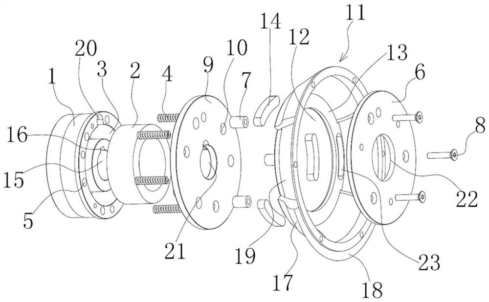
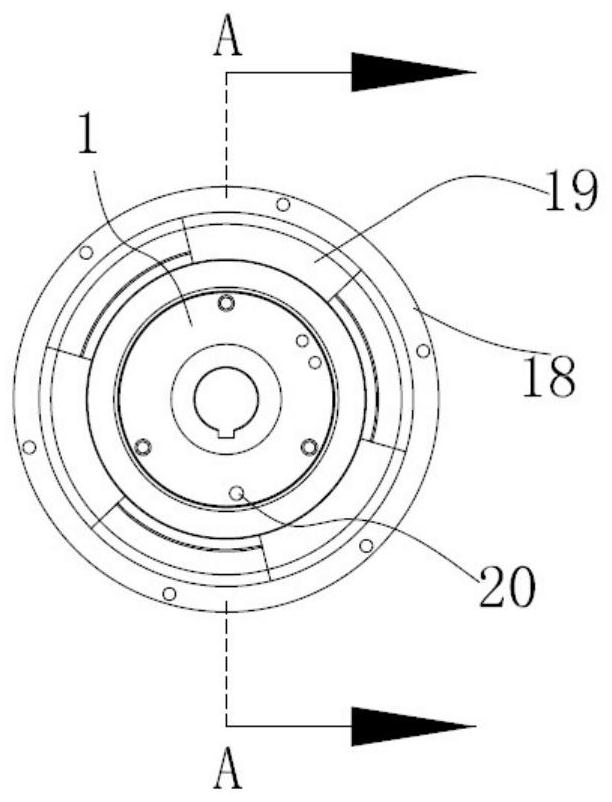
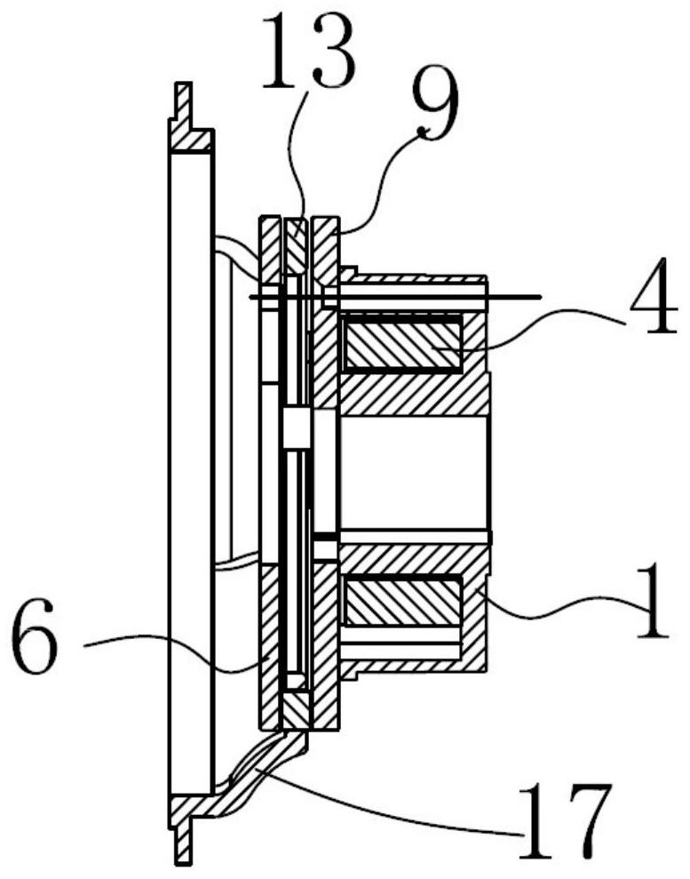
[0031] Depend on figure 1 , figure 2 , image 3 , Figure 4 and Figure 5 As shown, the iron core 1 is provided with an annular groove 3 for accommodating the coil winding 2, the iron core 1 is provided with a plurality of spring grooves 5 for accommodating the compression spring 4, the coil winding 2 is arranged in the annular groove 3, and the compression spring One end of 4 is embedded in the spring groove 5 of the iron core. The cover plate 6 and the iron core 1 are fixed to each other. The space is fixed by screws 8, and the screws 8 are screwed with the iron core 1 after the cover plate 6 passes through the contour column 7.

[0032] The armature 9 is interposed between the iron core 1 and the cover plate 6, the armature 9 has a through hole 10 matched with the outer diameter of the contour column 7 and is slidably connected between the iron core 1 and the cover plate 6, the other end of the compression spring 4 is connected to the One end face of the armature 9 is...

Embodiment 2

[0037] like Image 6As shown, the iron core 1 is provided with an annular groove 3 for accommodating the coil winding 2, the iron core 1 is provided with a plurality of spring grooves 5 for accommodating the compression spring 4, the coil winding 2 is arranged in the annular groove 3, and the compression spring One end of 4 is embedded in the spring groove 5 of the iron core. The cover plate 6 and the iron core 1 are fixed to each other. The space is fixed by screws 8, and the screws 8 are screwed with the iron core 1 after the cover plate 6 passes through the contour column 7.

[0038] The armature 9 is interposed between the iron core 1 and the cover plate 6, the armature 9 has a through hole 10 matched with the outer diameter of the contour column 7 and is slidably connected between the iron core 1 and the cover plate 6, the other end of the compression spring 4 is connected to the One end face of the armature 9 is offset; the brake disc 11 is interposed between the armatu...


PUM


Abstract

The invention relates to a high-reliability electromagnetic power-off brake which comprises a cover plate and a brake disc; the cover plate and an iron core are mutually fixed; a plurality of equal-height columns are arranged between the cover plate and the iron core for supporting; an armature is arranged between the iron core and the cover plate, is provided with through holes matched with the external diameters of the equal-height columns and is in sliding fit between the iron core and the cover plate; the other end of each of a plurality of compression springs is propped against one end face of the armature; the brake disc is arranged between the armature and the cover plate; a friction plate hole allowing a friction plate to penetrate through is formed in the brake disc; the brake disc is thinner than the friction plate; the friction plate is in loose fit with the friction plate hole; the upper and lower end faces playing the frictional role of the friction plate protrude out of the two end faces of the brake disc separately; when a coil winding is electrified, the brake disc freely rotates between the armature and the cover plate; and when the coil winding is powered off, theupper and lower end faces of the friction plate are in compressed frictional contact with the cover plate and the armature separately.

Description

technical field [0001] The invention relates to an electromagnetic power loss brake with high reliability. . Background technique [0002] The working principle of the electromagnetic power-off brake is that when the coil winding is energized, the magnetic force is generated so that the armature is sucked back against the force of the spring, and the brake disc can rotate freely; when the coil winding is de-energized, the magnetic force of the coil winding disappears, and the armature is drawn back. The spring pushes against the brake disc, and the friction plate generates friction between the brake disc and the armature to prevent the brake disc from rotating so as to play a braking role. [0003] Most of the existing electromagnetic brakes fix the friction plate on the surface of the brake disc. When the electromagnetic de-energized brake of this structure is assembled with the rotor, especially the outer rotor of the motor, it may be due to the machining accuracy of the ...

Claims


Application Information

Patent Timeline
Patent Type & Authority Applications(China)
IPC IPC(8): F16D55/02F16D65/16F16D121/20
CPCF16D55/02F16D65/16F16D2121/20
Inventor 杨俊杨海燕周章军
Owner ZHEJIANG INNUOVO HERTZ ELECTRIC CO LTD
Why Eureka
Try Eureka