A floating friction holding mechanism for the flange of the main reducer assembly

A main reducer and flange technology, which is applied in the field of the main reducer assembly flange floating friction gripping mechanism, can solve the problems of difficulty in guaranteeing reliability and compatibility, etc.

Active Publication Date: 2017-11-07
ANHUI JEE AUTOMATION EQUIP CO LTD
View PDF6 Cites 0 Cited by
  • Summary
  • Abstract
  • Description
  • Claims
  • Application Information

AI Technical Summary

Problems solved by technology

[0002] During the assembly process of the main reducer assembly, it is necessary to measure the backlash of the main gear and the back teeth. According to the measurement principle of the backlash, it must be ensured that the flange of the main reducer does not rotate, so there must be a feasible convex The flange clamping mechanism is used to measure the backlash of the teeth. In the previous design, we often designed the way of clamping the outer circle of the flange. When the processing quality of the flange is different, it is difficult to guarantee the reliability and compatibility of the outer circle clamping method of the flange.

Method used


Image

  • A floating friction holding mechanism for the flange of the main reducer assembly
  • A floating friction holding mechanism for the flange of the main reducer assembly
  • A floating friction holding mechanism for the flange of the main reducer assembly

Examples


Embodiment Construction

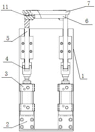
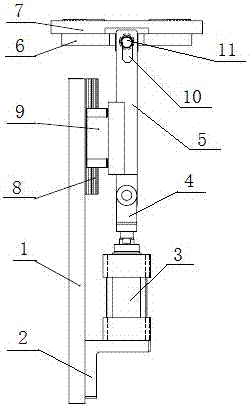
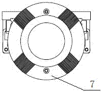
[0016] See figure 1 — image 3 , a main reducer assembly flange floating friction gripping mechanism, including a mounting plate 1, two cylinder bases 2 fixed on the mounting plate 1, two cylinders 3 installed on the corresponding cylinder bases 2, two The bottom end is connected to the piston rod of the corresponding cylinder 3 through the cylinder installation trunnion 4. The connecting rod 5 connected to the top of the two connecting rods 5 is connected to the clamping disc chassis 6, and the flange is fixed on the upper end surface of the clamping disc chassis 6. The tight disk 7, the guide rail 8 arranged on the mounting plate 1, and the slide block 9 slidably arranged on the guide rail 8, wherein the top ends of the two connecting rods 5 are connected to the outer circumference of the tight disk chassis 6 and arranged oppositely , the slider 9 is fixedly connected to the connecting rod 5, the top of the connecting rod 5 is provided with a waist hole 10, and the pin shaf...


PUM


Abstract

The invention discloses a main reducer assembly flange floating friction gripping mechanism, which comprises a mounting plate, a cylinder fixed on the mounting plate, a connecting rod whose bottom end is connected to the piston rod of the cylinder, and a connecting rod connected to the top end of the connecting rod. The tight disc chassis is fixed on the flange on the upper end surface of the tight disc chassis. The invention adopts the cylinder to drive the flange clamping disc to lift up and down, so that the flange clamping disc can be closely attached to the flange surface of the main reducer flange, thereby ensuring that the flange of the main reducer cannot rotate and play the role of frictional clamping . The invention can accommodate flanges of different sizes, shapes and heights, and has high stability.

Description

technical field [0001] The invention relates to the field of final reducers, in particular to a floating frictional gripping mechanism of a flange of a final reducer assembly. Background technique [0002] During the assembly process of the main reducer assembly, it is necessary to measure the backlash of the main gear and the back teeth. According to the measurement principle of the backlash, it must be ensured that the flange of the main reducer does not rotate, so there must be a feasible convex The flange clamping mechanism is used to measure the backlash of the teeth. In the previous design, we often designed the way of clamping the outer circle of the flange. When the processing quality of the flange is different, it is difficult to guarantee the reliability and compatibility of the outer circle clamping method of the flange. Contents of the invention [0003] The technical problem to be solved by the present invention is to provide a floating friction locking mecha...

Claims


Application Information

Patent Timeline
Patent Type & Authority Patents(China)
IPC IPC(8): F16D55/02F16D65/14F16D121/04
Inventor 刘蕾吴磊许伟明
Owner ANHUI JEE AUTOMATION EQUIP CO LTD
Why Eureka
Try Eureka