A high-frequency inverter power supply with a protective mechanism
A high-frequency inverter, protection mechanism technology, applied in the transformation of equipment structural parts, irreversible DC power input into AC power output, electrical components and other directions, can solve the problem of high-frequency inverter power failure, high-frequency inverter The power supply does not have self-protection performance, self-protection and other problems to achieve the effect of improving self-protection ability
- Summary
- Abstract
- Description
- Claims
- Application Information
AI Technical Summary
Problems solved by technology
Method used
Image
Examples
Embodiment 1
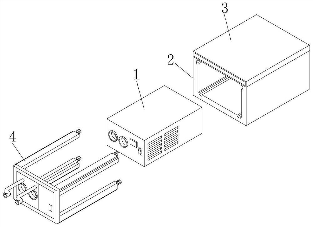
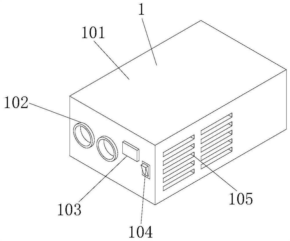
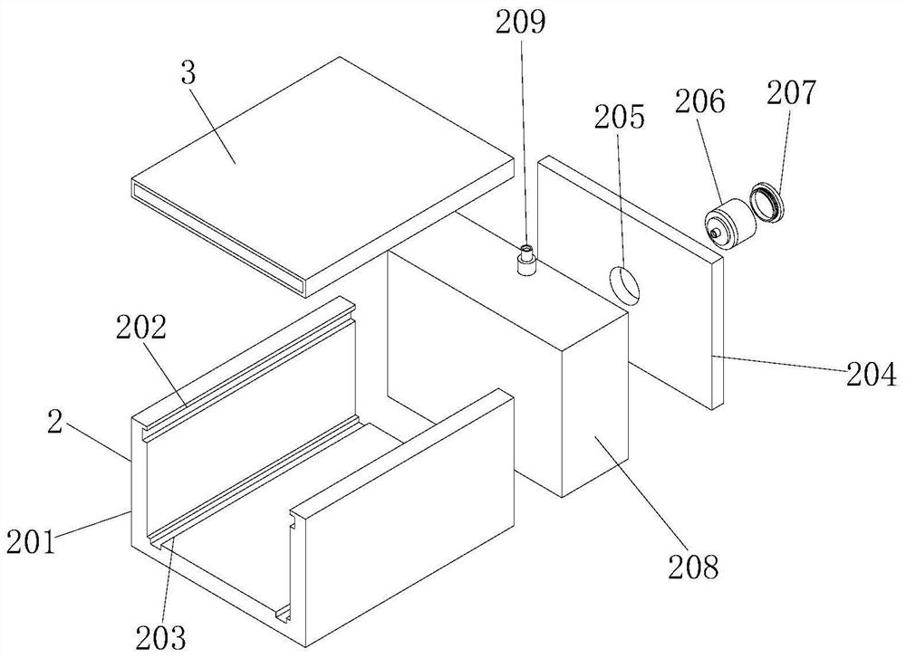
[0040] refer to Figure 1-Figure 7 , a high-frequency inverter power supply with a protective mechanism, including an inverter power supply inner shell device 1, an outer shell device 2, a top cover device 3 and a movable device 4, the rear of the inverter power supply inner shell device 1 is provided with an outer shell device 2, The shell device 2 includes a shell 201, the shape of the shell 201 is U-shaped, the upper side of the left and right inner walls of the shell 201 is provided with a limit groove 1 202, and the lower inner wall of the shell 201 is provided with a limit groove 2 203, and the limit groove 2 203 The number is two, and the two limiting slots 203 are respectively located on the left and right sides of the lower inner wall of the housing 201. The rear end of the housing 201 is fixedly connected with a rear plate 204, and the front surface of the rear plate 204 is provided with a through hole 205. The through hole 205 The inside of the air valve 206 is fixe...
Embodiment 2
[0049] refer to Figure 4-6 , a high-frequency inverter power supply equipped with a protective mechanism, which is basically the same as Embodiment 1, and furthermore, the difference is that chute 306 is provided on the left and right inner walls of the lower plate of the top cover 301, and the lower plate of the top cover The inside of 301 is provided with baffle plate 307, and baffle plate 307 is adapted with the inside of top cover lower plate 301, and the left and right sides rear ends of baffle plate 307 are all provided with connecting plate 308, and the front end of connecting plate 308 is connected with the rotation through bearing rotation. Shaft 309, the rotating shaft 309 is fixedly connected to the baffle plate 307 at the end away from the connecting plate 308, the baffle plate 307 and the connecting plate 308 are rotatably connected through the rotating shaft 309, and the connecting plate 308 is on the side close to the inner wall of the lower plate 301 of the top...
Embodiment 3
[0052] refer to figure 1 and Figure 7 , a high-frequency inverter power supply with a protective mechanism, which is basically the same as that of Embodiment 1. The difference is that the front surface of the front plate 401 is fixedly connected with a positioning hole 412, and the positioning hole 412 is embedded in the front plate 401. The positioning hole 412 is directly opposite to the socket 102, and an L rod 408 is arranged above the positioning hole 412. The rear end of the L rod 408 is inserted into the inside of the front plate 401, and the end of the L rod 408 is fixedly connected to the front plate 401. There is a wire fixing device 409, which is directly opposite to the center of the positioning hole 412. A transparent plate 410 is fixedly installed on the right side of the front surface of the front plate 401. The transparent plate 410 is made of transparent material. The transparent plate 410 and the indicator light 103 The position of the transparent plate 410...
PUM
 Abstract
Description
Claims
Application Information
 - R&D
- Intellectual Property
- Life Sciences
- Materials
- Tech Scout
- Unparalleled Data Quality
- Higher Quality Content
- 60% Fewer Hallucinations
Browse by: Latest US Patents, China's latest patents, Technical Efficacy Thesaurus, Application Domain, Technology Topic, Popular Technical Reports.
© 2025 PatSnap. All rights reserved.Legal|Privacy policy|Modern Slavery Act Transparency Statement|Sitemap|About US| Contact US: help@patsnap.com


