
Edge image extraction method and system based on correlated imaging

An edge image and correlation imaging technology, applied in image enhancement, image analysis, image data processing and other directions, can solve the problem of edge image thick

Inactive Publication Date: 2020-11-20
NAT UNIV OF DEFENSE TECH
View PDF7 Cites 4 Cited by
  • Summary
  • Abstract
  • Description
  • Claims
  • Application Information

AI Technical Summary

Problems solved by technology

[0006] Aiming at the deficiencies of the prior art, the present invention provides an edge image extraction method based on correlation imaging, which solves the existing technical problem that the edge of the target edge image obtained by direct reconstruction based on the gradient magnitude information is relatively thick

Method used


Image

  • Edge image extraction method and system based on correlated imaging
  • Edge image extraction method and system based on correlated imaging
  • Edge image extraction method and system based on correlated imaging

Examples


Embodiment 1

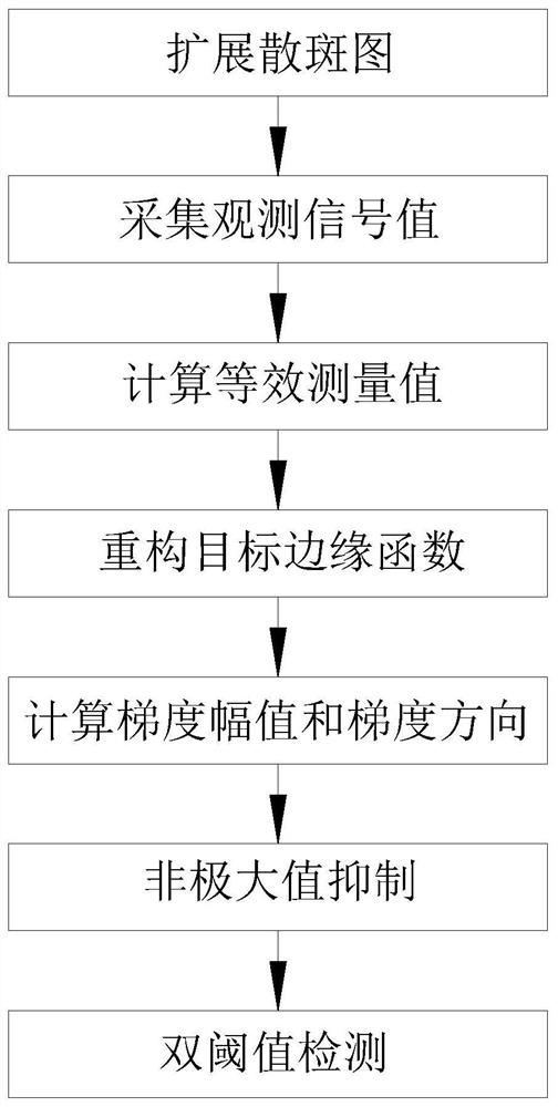
[0059] Embodiments of the present invention first propose a method for extracting edge images based on associated imaging, such as figure 1 As shown, the method includes:

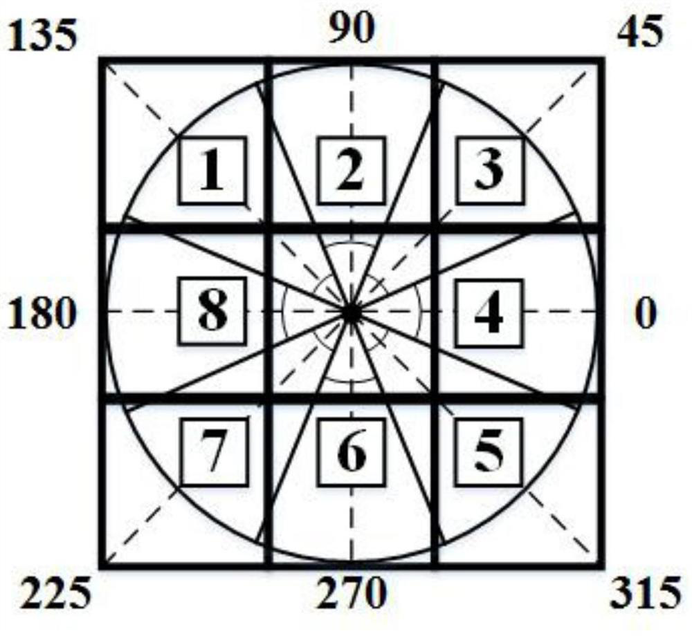
[0060] S1. In the k-th sampling, M pieces of speckle patterns S with sparse random distribution are obtained k (x,y), and then expand each speckle pattern into a set of speckle modulation maps

[0061] S2, the speckle modulation map Sequentially loaded onto the digital micromirror device to modulate the illuminated light field reflected by the target, and obtain a set of observed signal values ​​through a single-pixel detector

[0062] S3, using the observed signal value Compute equivalent measurements for vertical edges and equivalent measurements of the horizontal edge Complete a sampling;

[0063] S4. After completing M times of sampling, the equivalent measurement value based on the vertical edge and equivalent measurements of the horizontal edge And the spatial distribution function ...

Embodiment 2

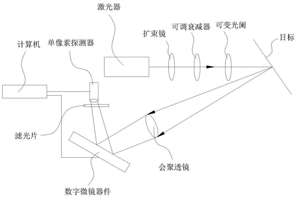
[0115] Another embodiment of the present invention also proposes a system for extracting edge images based on associated imaging using the method, such as figure 2 shown, including:

[0116] A continuous light tunable custom laser, a digital micromirror device, a single-pixel detector, and a computer respectively communicating with the single-pixel detector and the digital micromirror device;

[0117] The computer includes a memory, a processor, and a computer program stored on the memory and operable on the processor, and the processor implements steps S1-S7 when executing the program;

[0118] A beam expander, an adjustable attenuator, an iris, a target, a converging lens, a digital micromirror device, and an optical filter are sequentially arranged on the optical path between the continuous light tunable customized laser and the single-pixel detector.

[0119] In this embodiment, a continuous light tunable custom laser, a beam expander, an adjustable attenuator, an iris, ...


PUM

PropertyMeasurementUnit
Focal lengthaaaaaaaaaa
Caliberaaaaaaaaaa

Abstract

The invention provides an edge image extraction method and system based on correlated imaging, and relates to the technical field of edge image extraction. The method comprises the following steps: acquiring an observation signal value and a corresponding illumination light field intensity distribution function Ik(x, y) based on an imaging system; calculating the sum of equivalent measurement values; reconstructing a vertical edge function Nabla Rv(x, y) and a horizontal edge function Nabla Rh(x, y) of the target; calculating the gradient amplitude Nabla R(x, y) and the gradient direction theta(x, y) of the target; refining the edge and suppressing edge blur by adopting non-maximum suppression, eliminating a pseudo edge and discontinuous lines generated by non-maximum suppression through double-threshold detection, and finally, directly extracting a clear edge image of a thin edge, thereby being beneficial to accurate extraction of angular point information of the target in the later period.

Description

technical field [0001] The invention relates to the technical field of edge image extraction, in particular to an edge image extraction method and system based on correlation imaging. Background technique [0002] Edge images are the basis for image processing and machine vision to realize recognition, judgment, tracking and restoration of targets. For example, corner information of targets can be obtained based on edge images. How to extract clear edge images by correlative imaging system is the key technology to promote the practicality of correlative imaging technology. [0003] The existing edge image extraction method based on correlation imaging (hereinafter referred to as the prior art) usually uses the correlation imaging system to obtain the measurement value, then calculates the equivalent measurement value and gradient magnitude information, and finally directly reconstructs the gradient magnitude information based on the obtained The edge image of the target. ...

Claims


Application Information

Patent Timeline
IPC IPC(8): G06T7/13G06T7/136
CPCG06T7/13G06T7/136G06T2207/20164
Inventor 程正东陈熠朱斌杨华李晓霞白秀军解博朱耀轩吴梦醒
Owner NAT UNIV OF DEFENSE TECH
Learn More